Build a Sound-Activated RGB LED with Arduino
Connect a sound sensor and an RGB LED to your Arduino. Every time the sensor detects a loud enough sound — like a clap — the LED cycles to a new color. You will learn how digital sensors produce a falling edge, why that edge needs to be caught only once, and how to prevent a single clap from registering as five.
Live project track
Clap once. The LED changes color. Clap again. It changes again. This project sounds simple, but it hides two ideas that show up in almost every sensor-driven project you will ever build: how to catch a single event from a noisy signal, and how to stop that event from firing five times when you only intended once.
What DOUT Actually Sends When You Clap
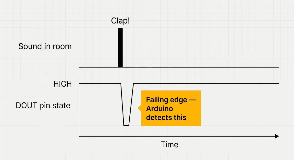
The sound sensor has two outputs. The analog one (AOUT) sends a continuously changing voltage that follows the room's noise level. We are not using that here. The digital one (DOUT) behaves differently — it normally sits at HIGH (5V) and briefly drops to LOW (0V) the moment the sound level crosses the threshold set by the small trimmer on the board.
That moment when the pin goes from HIGH to LOW is called a falling edge. It is the exact instant the Arduino needs to catch. Not the LOW state itself — just the transition. If the code only watches for LOW, it would trigger continuously for as long as the sound lasts. Watching for the falling edge means it triggers exactly once per sound event.
Why One Clap Produces Many Pulses
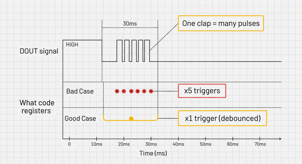
Here is the problem: a real hand clap does not produce a single clean pulse. The sound bounces off walls, the microphone rings slightly after the initial impact, and the sensor may cross the threshold multiple times within the same 20”“30 milliseconds. Without any protection, one clap can register as five or six separate falling edges — and the LED color jumps five or six steps instead of one.
This effect is called bouncing, and the solution is called debouncing. After the first falling edge is detected, the code sets a timestamp and ignores all further triggers for the next 150 milliseconds. By the time that window closes, the echo and ring have settled, and the sensor is back to a stable HIGH.
If the LED color jumps multiple steps on a single clap, the debounce window is too short. Try increasing debounceMs from 150 to 250 and test again.Wiring the Sensor and RGB LED Together
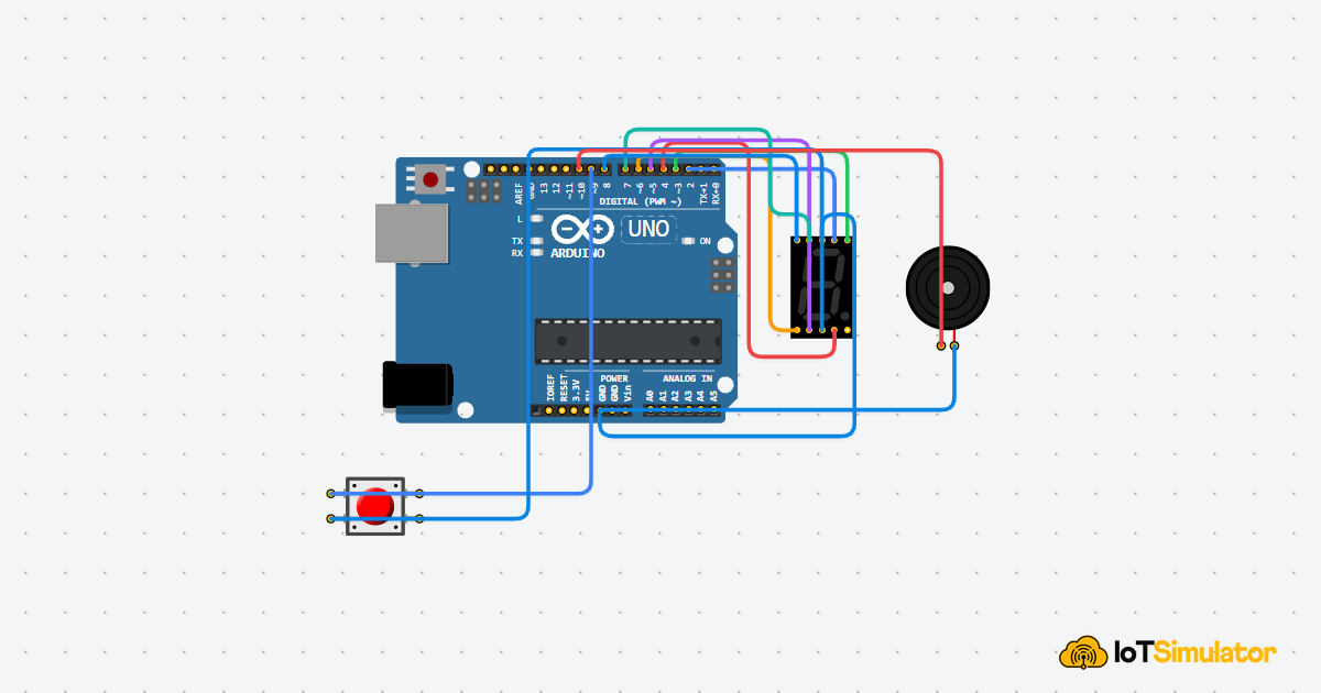
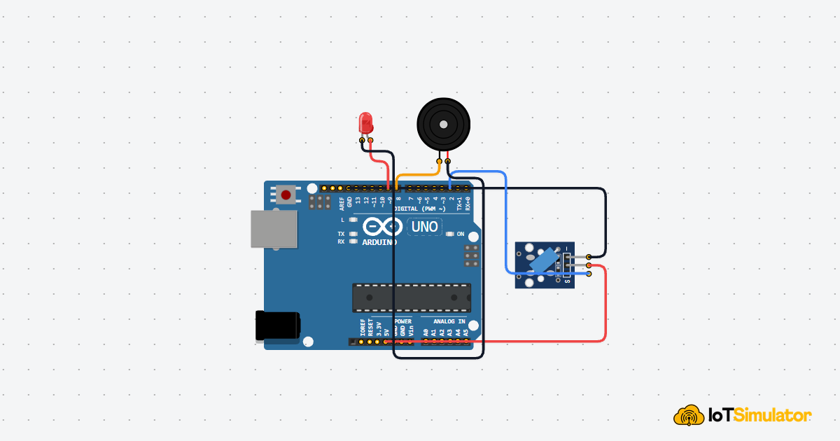
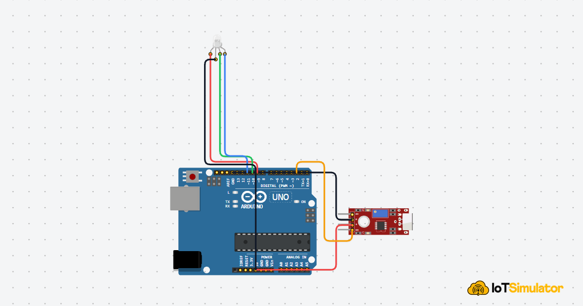
This project has two components wired independently to the Arduino. The sound sensor connects to a single digital input pin. The RGB LED connects to three PWM output pins and one shared power line.
Powers the sensor module.
Shared ground reference.
Digital falling-edge signal — this is the pin the code monitors.
Red channel — PWM pin for brightness control.
Green channel — PWM pin for brightness control.
Blue channel — PWM pin for brightness control.
Common anode — the shared positive rail for all three channels.
If the colors look inverted — for example the LED turns on when it should be off — your RGB LED is common cathode, not common anode. Connect COM to GND and remove the value inversion in setColor().
Why Common Anode Inverts the PWM Values
The RGB LED in this project uses a common anode design — meaning the shared pin is connected to 5V (the positive rail), and each color channel pin controls how much of that voltage flows through by pulling it toward ground. A fully-on channel gets a value of 0 (connected to ground) and a fully-off channel gets 255 (same voltage as the anode, so no current flows).
This is the opposite of what you might expect. When you want red at full brightness, you write 0 to the red pin, not 255. That is why setColor() subtracts every value from 255 before calling analogWrite(). It flips the logic so the rest of the code can work with intuitive values like setColor(255, 0, 0) for red.
How the Falling Edge and Debounce Work in Code
The main loop reads the sensor pin on every iteration and compares it to the value from the previous iteration. A falling edge is exactly the combination where last reading was HIGH and the current reading is LOW. That condition only becomes true once — at the exact moment of the transition — no matter how long the signal stays LOW afterward.
Why millis() Instead of delay() for the Debounce Window
The debounce window uses millis() to track time, not delay(). This distinction matters. A delay(150) would freeze the entire Arduino for 150ms — it would stop reading the sensor, stop updating any other output, stop everything. By recording the time of the last trigger with millis() and comparing it on every loop, the Arduino keeps running normally and simply ignores triggers that arrive too close together.
This pattern — check elapsed time instead of blocking — is fundamental to writing responsive Arduino code. Any project that needs to react to two things at once relies on it.
How the Color Array Cycles Without an if-Chain
The six colors are stored in a 2D array where each row is one color as [red, green, blue] values. colorIndex tracks which row is currently active. On each valid clap, the index increments by 1. The % totalColors operation wraps it back to 0 after the last color — so the sequence loops automatically without any additional logic.
Adjusting the Sensor Sensitivity for Your Room
The sound sensor has a small blue trimmer potentiometer on the board. Turning it clockwise raises the detection threshold — the sensor becomes less sensitive and only responds to louder sounds. Turning it counter-clockwise lowers the threshold — it becomes more sensitive and may trigger on background noise like speech or footsteps.
There is no single correct setting. The right position depends on your room's background noise level and how far away you plan to clap. A good starting point is to turn the trimmer to its midpoint, clap from about 50cm away, and adjust from there until single claps trigger reliably without background noise causing false triggers.
Taking It Further
- Add a buzzer that beeps once each time a clap is detected — audio confirmation that the trigger registered.
- Change the color array to use only two colors and toggle between them, like a simple clap-on / clap-off light switch.
- Add a second sound sensor pointing in a different direction so the project responds to claps from anywhere in the room.
- Use the analog output (
AOUT) instead ofDOUTto make the LED brightness respond proportionally to how loud the room is.