Turn Movement into an Alarm with Arduino
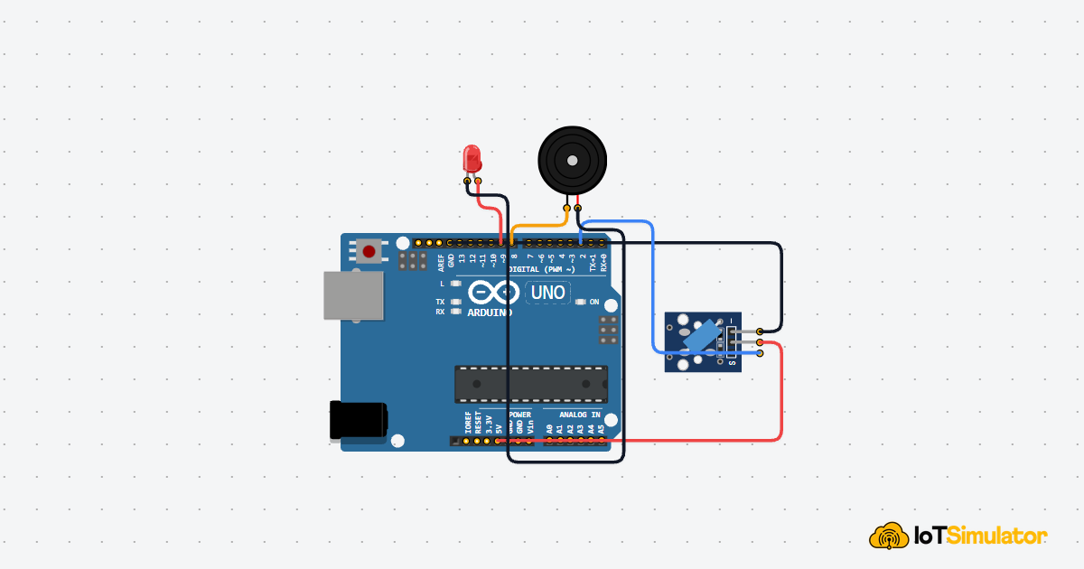
Build a small tilt alarm box with an Arduino Uno, a tilt switch, an LED, and a buzzer. The Arduino watches the tilt switch, confirms that the box has moved, then turns on both visual and sound alerts.
Live project track
Imagine a small box sitting quietly on a table. If someone picks it up, tips it over, or shakes it, you want the box to complain immediately. That is the idea behind this project: movement becomes a warning.
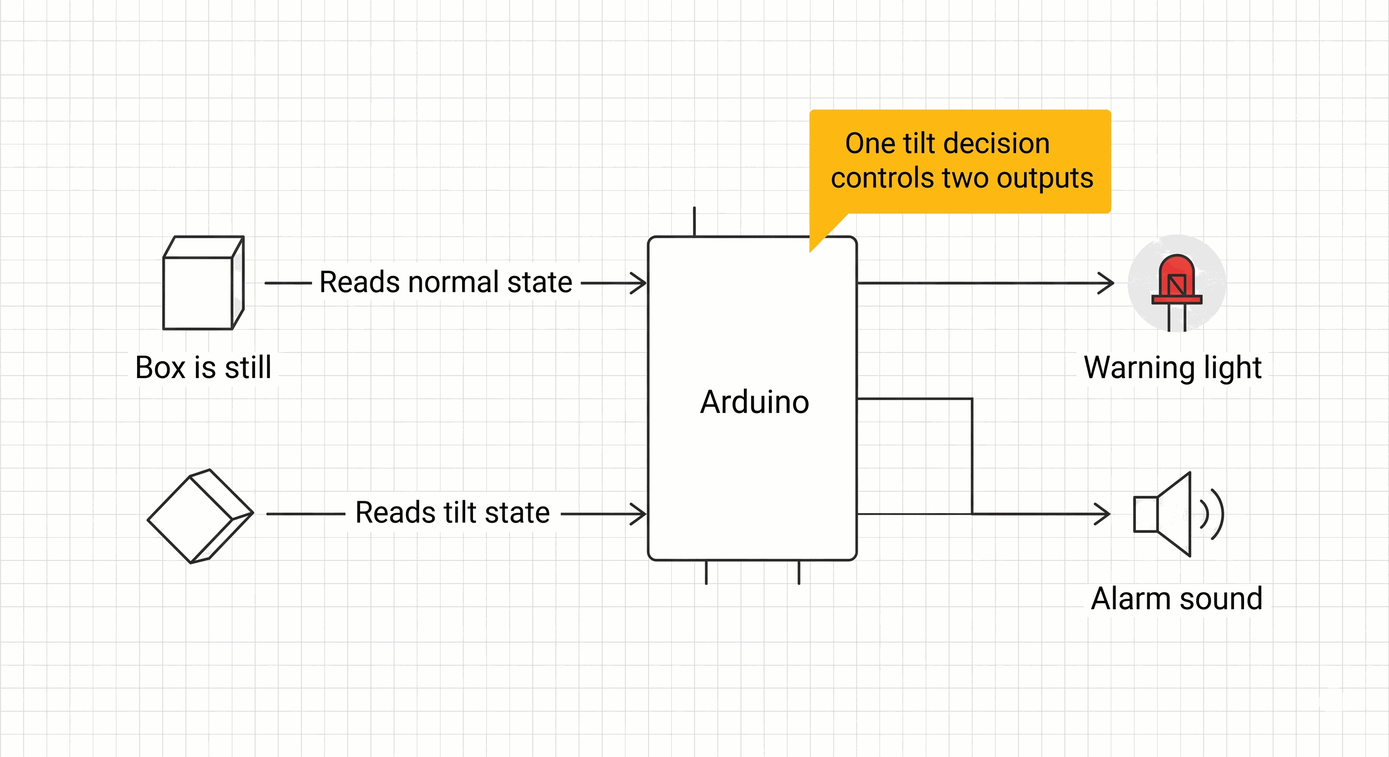
In this project, you will build a simple tilt alarm box with an Arduino Uno, a tilt switch, a red LED, and a buzzer. The main concept is beginner-friendly: a physical tilt can become a digital input, and one digital decision can turn on multiple outputs.
A Tilted Box Becomes a Digital Decision
A tilt alarm does not need to measure the exact angle of the box. It only needs to answer one yes-or-no question: has the box moved from its normal position? That makes a tilt switch a good first movement sensor.
The Arduino reads the tilt switch as a digital input. Digital means the reading is treated as one of two states, like on or off. In this project, the normal state keeps the alarm quiet. The tilted state turns on the LED and buzzer together.
| Box condition | Arduino decision | Outputs |
|---|---|---|
| Box is still | No tilt detected | LED off, buzzer quiet |
| Box is tilted | Tilt detected | LED on, buzzer sounding |
| Box returns to normal | No tilt detected again | Alarm turns off |
This project is useful because it turns an invisible program decision into something you can see and hear. The LED gives a visual warning, while the buzzer makes the alarm hard to miss.
Gravity Moves the Contact Inside the Tilt Switch
A tilt switch behaves a little like a tiny rolling object inside a tube. When the module sits one way, the internal contact makes a connection. When the module tilts, gravity moves the contact and the connection changes.
That is why this component feels simple from the Arduino side. The Arduino does not need to calculate motion, speed, or angle. It only checks whether the switch output is in the alarm state or the safe state.
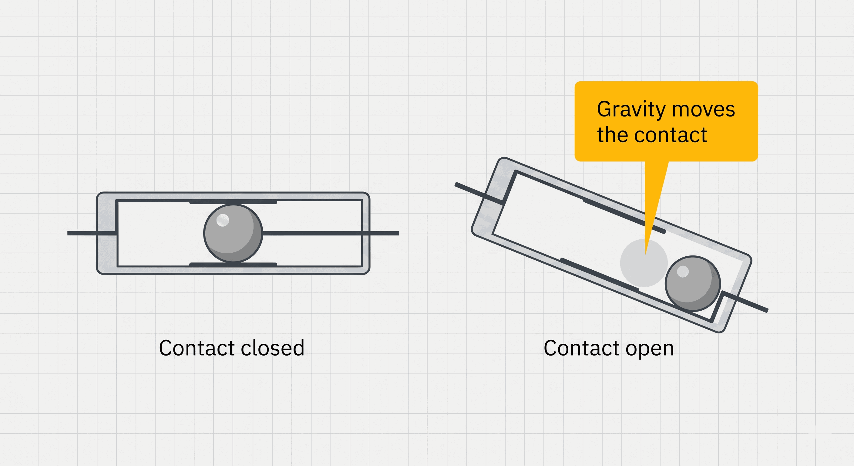
A tilt switch is closer to a button than a motion tracker. It tells the Arduino that the physical state changed, not exactly how far or how fast the box moved.
The simulator version exposes this same idea through the tilt control. When the tilt state changes, the OUT pin changes state, and the sketch reacts just like it would with a physical switch module.
A Short Confirmation Delay Keeps the Alarm From Flickering
Mechanical switches can rattle for a tiny moment when they change state. The contact may close, open, and close again before it settles. This is called bounce. If the code reacts to the first tiny change immediately, the alarm may flicker or chirp briefly.
This beginner sketch uses a very simple confirmation step. It reads the tilt switch once, waits 80 milliseconds, then reads it again. The alarm turns on only when both readings say the box is tilted. That tiny pause gives the contact time to settle.
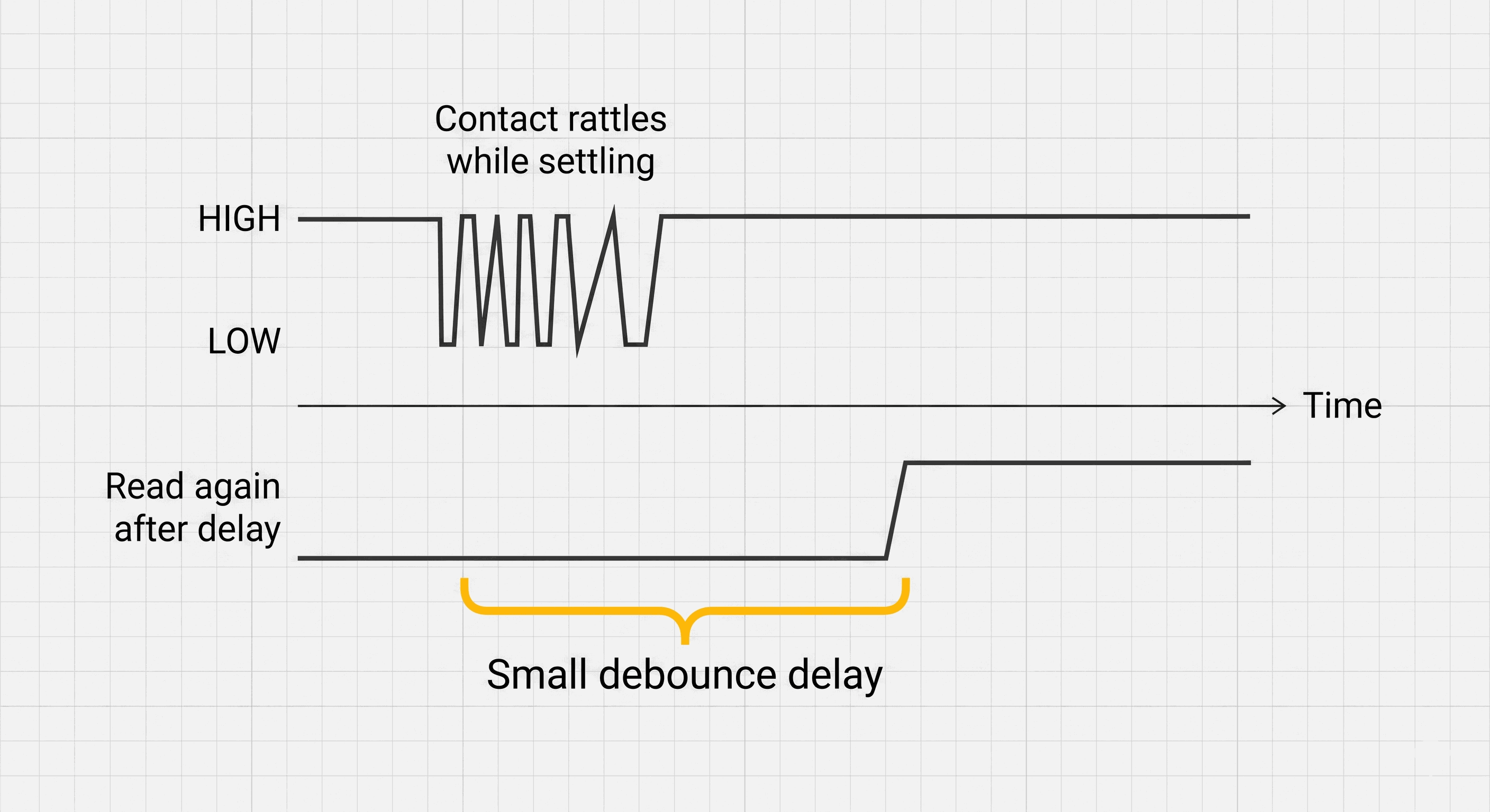
- First read notices that the switch may have changed.
- Short delay gives the mechanical contact time to settle.
- Second read confirms whether the alarm should really turn on.
This is not the most advanced debounce method, but it is perfect for a first alarm box. The box does not need millisecond-level speed. It needs a clean and understandable warning when the tilt state is real.
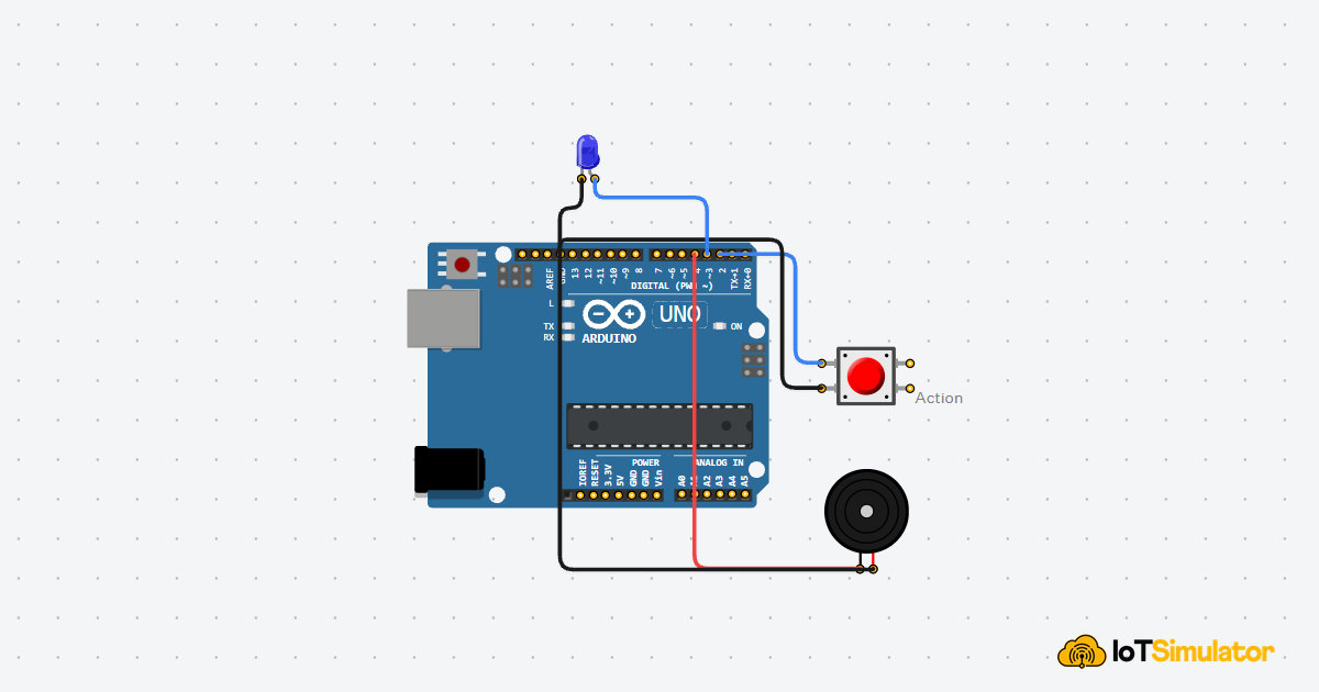
Each Wire Gives the Tilt Alarm One Job
The circuit has three parts. The tilt switch is the input, because it tells the Arduino whether the box moved. The LED and buzzer are outputs, because the Arduino controls them after making the decision.
5V is the positive power supply from the Arduino. GND is the return path for electricity, like the negative terminal of a battery. Every component needs the right power and ground reference so the Arduino can read or control it reliably.
Powers the tilt switch module.
Shares the same return path and voltage reference as the Arduino.
Carries the tilt state into the Arduino as a digital input.
Receives the HIGH output signal that turns the LED on.
Completes the LED circuit back to ground.
Receives the tone signal that creates the alarm sound.
Completes the buzzer circuit back to ground.
In a real LED circuit, add a current-limiting resistor in series with the LED. The simulator is forgiving, but real LEDs should not be connected directly without protection.
The Complete Tilt Alarm Box Sketch
The code uses named constants for every pin and timing value. This keeps the sketch readable: tiltPin says what the pin does, and settleDelayMs explains why the delay exists.
The alarm logic is intentionally small. Read the switch, confirm it after a short delay, then turn the outputs on or off. That makes the project easy to understand and easy to modify later.
How the Tilt Alarm Code Works, Part By Part
Now let us break the sketch into the small decisions that make the alarm work. Each part has one job: name the pins, prepare the input and outputs, confirm the tilt, and trigger the warning.
▸ Tilt Alarm Pins Name the Sensor and Alerts
The sketch starts by naming the Arduino pins. Pin numbers are the physical connectors on the board. Giving them names keeps the sketch easier to read than writing raw numbers everywhere.
alarmToneHz controls the pitch of the buzzer. Hz means cycles per second, so a higher number makes a higher-pitched sound. settleDelayMs is the short wait used to confirm the tilt reading.
▸ Setup Prepares One Input and Two Outputs
In setup(), the tilt pin is configured as INPUT_PULLUP. INPUT means the Arduino listens to the pin, and the pull-up keeps the input stable when the switch is not pulling it LOW. The LED and buzzer are OUTPUT pins because the Arduino controls them.
▸ Two Reads Confirm the Box Really Moved
The loop reads the tilt switch, waits briefly, and reads it again. If the contact was only bouncing, the two readings may not match. If the box is truly tilted, both readings should show the alarm state.
▸ LOW Reading Turns On Both Warnings
Because this setup uses a pull-up input, the alarm state is LOW. LOW means the pin is near 0V, so the switch has pulled the input toward ground. When both reads are LOW, the code turns the LED on and starts the buzzer tone.
HIGH on the LED pin means the Arduino sends voltage to the LED, so it lights up. tone() makes the buzzer vibrate at the chosen frequency. If the tilt is not confirmed, the LED turns off and noTone() silences the buzzer.
Adjusting the Tilt Alarm For Your Box
If the alarm flickers when the box is barely moving, increase settleDelayMs from 80 to 120. That gives the mechanical contact more time to settle before the second read. If the alarm feels too slow, reduce the value carefully.
If the buzzer pitch feels too harsh, lower alarmToneHz. A value around 800 sounds deeper, while 1500 or higher sounds sharper. The logic stays the same; only the sound changes.
Taking It Further
Once the tilt alarm works, you can add a reset button so the alarm stays on until someone acknowledges it. That would turn this from an instant alarm into a latch-style security box.
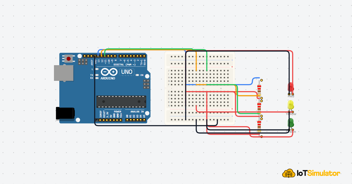
You can also replace the LED with an RGB LED. Green could mean safe, yellow could mean movement detected briefly, and red could mean confirmed tilt alarm.