Arduino Ultrasonic Parking Distance Alert
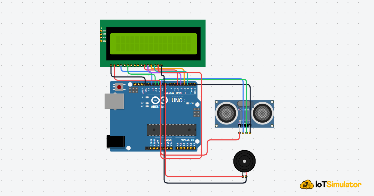
Build a simple parking helper with an HC-SR04 ultrasonic sensor, an LCD1602 display, and a buzzer. The Arduino measures how far an object is, shows the distance on the LCD, and changes the warning sound as the object gets closer.
Live project track
Have you ever listened to a car parking sensor beep faster as the bumper gets closer to a wall? That sound is not magic. The car is measuring distance again and again, then turning that number into a warning you can understand without looking away.
In this project, you will build the beginner version of that idea with an Arduino Uno, an HC-SR04 ultrasonic sensor, an LCD1602 display, and a buzzer. The one main concept is simple: the Arduino can measure how long an echo takes to come back, then use that time to decide whether the object is safe, close, or too close.
Echo Timing Becomes a Distance Reading
Think of shouting across an empty room. If the wall is close, your echo comes back quickly. If the wall is far away, the echo takes longer. The HC-SR04 works in the same familiar way, except it uses ultrasonic sound. Ultrasonic means sound that is too high-pitched for humans to hear.
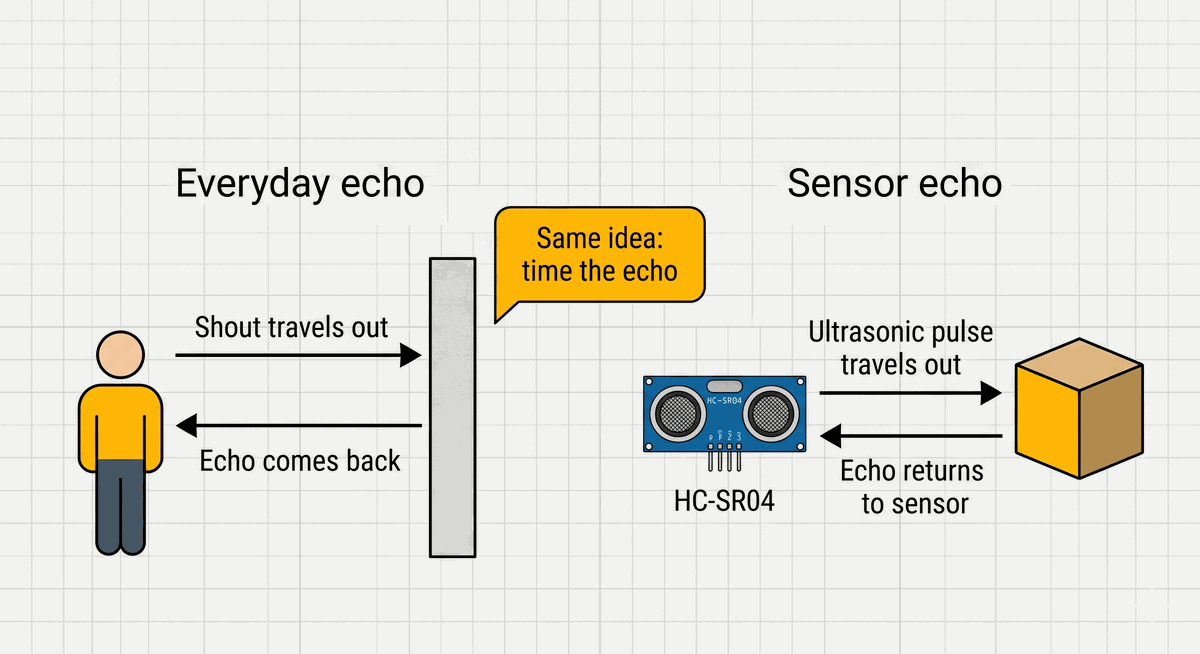
| Everyday echo | HC-SR04 sensor |
|---|---|
| You make a sound. | The sensor sends an ultrasonic pulse. |
| The sound hits a wall. | The pulse hits the object in front of the sensor. |
| The echo comes back to your ears. | The echo comes back to the sensor receiver. |
| A longer wait means the wall is farther away. | A longer ECHO pulse means the object is farther away. |
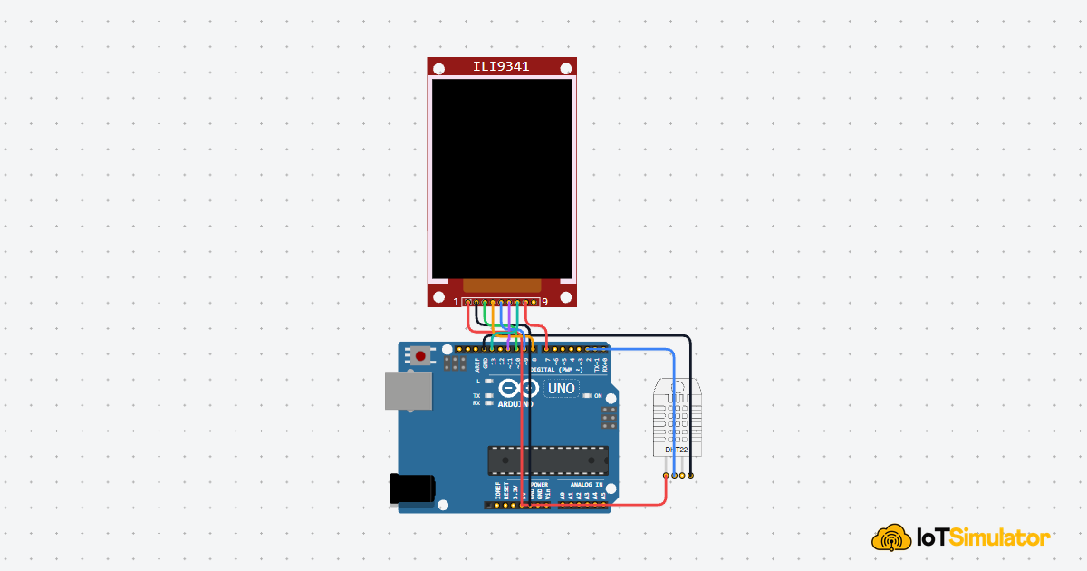
The sensor has two round metal cans on the front. One side sends a short sound burst, and the other side listens for the echo that bounces back. You do not need to hear that sound yourself. The sensor handles the sound, and the Arduino only watches the timing signal that comes back from the sensor.
The Arduino starts one measurement by sending a tiny signal to the TRIG pin. Think of TRIG as the start button for the sensor. The sensor answers on the ECHO pin by holding that pin HIGH while it waits for the sound to travel out and return.
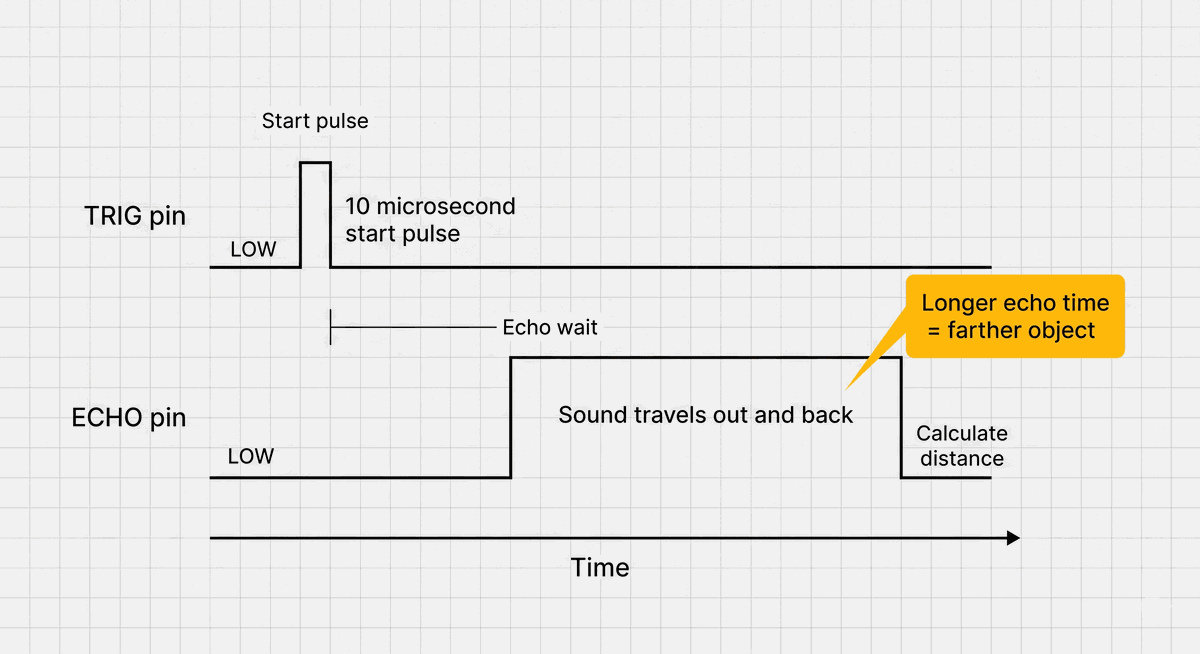
The Arduino is not measuring the sound directly. It is measuring how long the ECHO pin stays HIGH after the sensor sends the sound pulse.
HIGH means the pin is near 5V, so the Arduino reads it as on. LOW means the pin is near 0V, so the Arduino reads it as off. The longer the ECHO pin stays HIGH, the longer the sound was traveling. That time is the raw clue the Arduino uses to calculate distance.
Turning Round Trip Time Into One-Way Distance
The echo time measures the full round trip. Sound leaves the sensor, hits the object, and returns to the sensor. That is like walking from your chair to a wall and then walking back again. If you timed the whole walk, you would need to divide the time in half to know how long the one-way trip took.
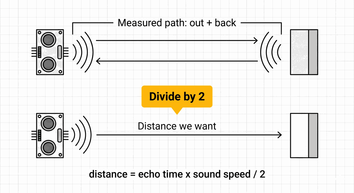
The distance calculation does the same thing. First, the code multiplies the echo time by the speed of sound in centimeters per microsecond. Then it divides by 2 so the LCD shows the distance from the sensor to the object, not the full there-and-back travel path.
The constant soundSpeedCmPerMicrosecond is set to 0.0343. That means sound travels about 0.0343 centimeters in one microsecond in normal room air. You do not need to memorize this number. For this beginner project, it is simply the conversion value that turns echo time into a useful distance reading.
- Echo time is the measured HIGH time from the ECHO pin.
- Sound speed turns that time into a travel distance.
- Divide by 2 removes the return trip so we get the one-way distance.
Three Distance Zones Make the Warning Easy to Read
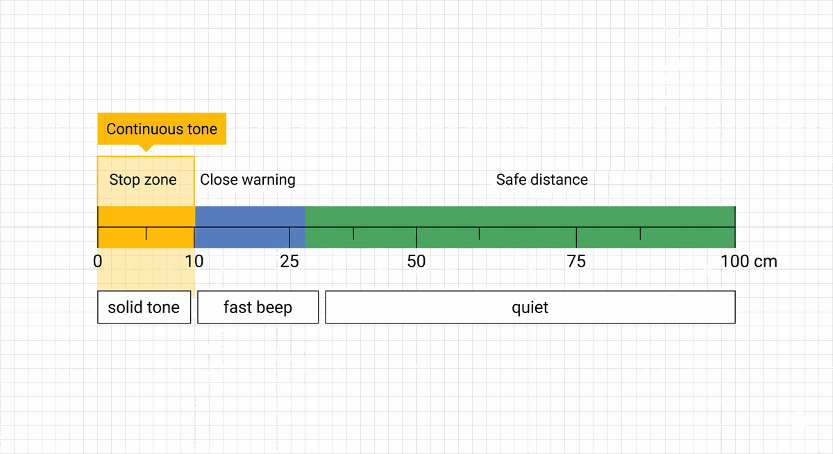
A parking sensor is useful because it turns a changing number into an easy warning. Reading 37 cm, 24 cm, and 9 cm on a screen takes attention. Hearing the buzzer change is faster. That is why this project groups the distance into three simple zones.
When the object is farther than 25 cm, the project shows Safe zone on the LCD and keeps the buzzer quiet. When the object is between 10 cm and 25 cm, the buzzer beeps quickly. When the object is 10 cm or closer, the buzzer becomes a steady tone and the LCD shows STOP.
These numbers are beginner-friendly starting points, not fixed rules. They are short enough to test on a desk with your hand, a notebook, or a small box. Later, you can change the threshold values in the code to make the warning start earlier or later.
| Distance | LCD message | Buzzer behavior | Meaning |
|---|---|---|---|
| More than 25 cm | Safe zone | Quiet | The object is far enough away. |
| 10 cm to 25 cm | Too close | Fast beep | The object is getting close. |
| 10 cm or less | STOP | Continuous tone | The object is too close. |
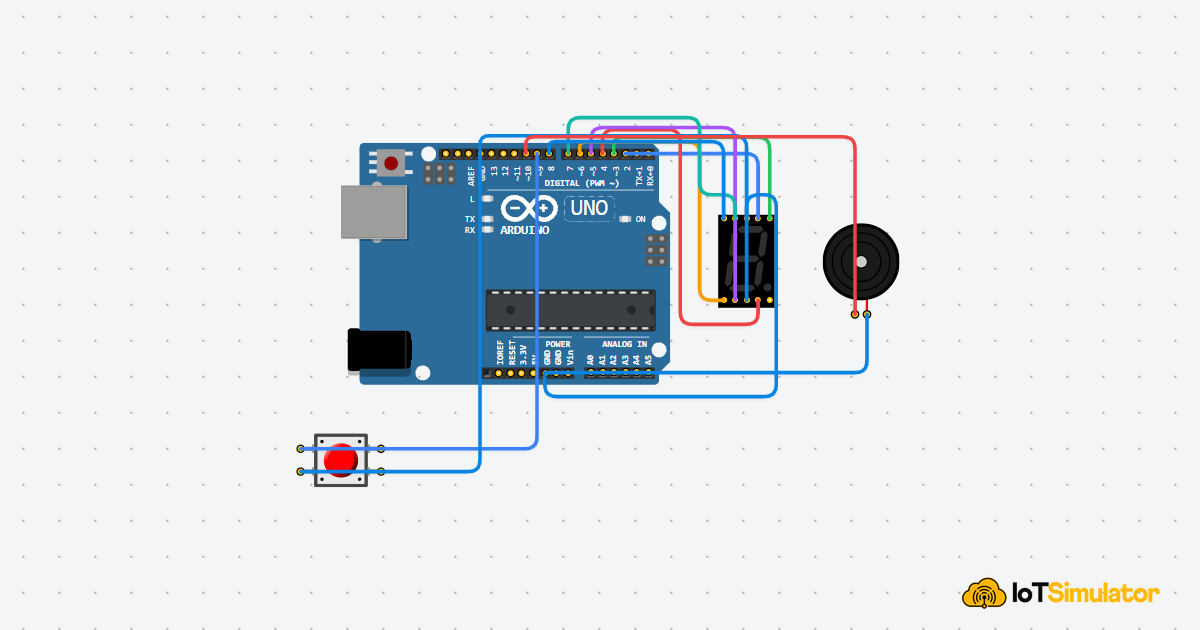
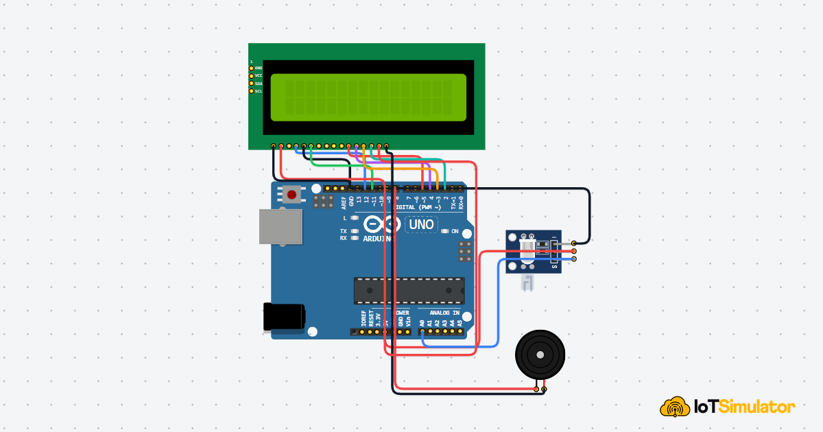
Each Wire Has One Job in the Alert System
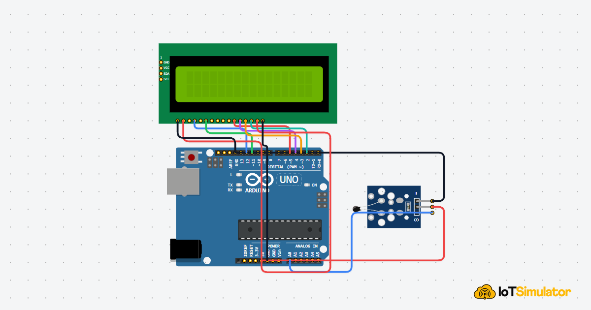
This circuit may look busier than a single LED project, but each group of wires has a simple role. The HC-SR04 measures distance, the LCD shows the reading, and the buzzer makes the warning sound. The Arduino sits in the middle and makes the decision.
5V is the positive power supply from the Arduino. It is where the sensor and LCD get the electricity they need to run. GND is the return path for that electricity, like the negative terminal of a battery. Components must share GND with the Arduino so they agree on what 0V means.
Powers the ultrasonic transmitter, receiver, and timing circuit.
Shares the same return path and voltage reference as the Arduino.
Receives the short start pulse from the Arduino.
Sends back the HIGH pulse that the Arduino measures.
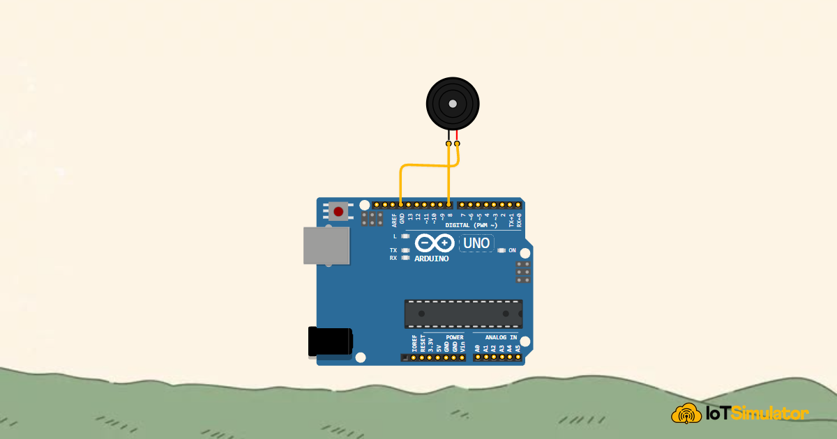
Receives the tone signal that creates the warning sound.
Completes the buzzer circuit back to ground.
Ground for the LCD logic.
Power for the LCD logic.
Chooses whether the LCD receives a command or display text.
Tells the LCD to accept the current data.
First data line used by the display.
Second data line used by the display.
Third data line used by the display.
Fourth data line used by the display.
Power for the LCD backlight.
Ground for the LCD backlight.
If the LCD lights up but shows no text, the problem is often contrast or one of the LCD data wires. Check the display wiring before changing the distance code.
The Complete Parking Alert Sketch
The code uses named constants like trigPin, echoPin, and stopDistanceCm. A constant is a value that the sketch can read but does not change while the program runs. Naming these values makes the code read like a set of project decisions instead of a pile of numbers.
This matters when you tune the alert. If the buzzer starts too late, you change warningDistanceCm. If the stop tone should begin earlier, you change stopDistanceCm. You do not need to hunt through the sketch wondering which number controls which behavior.
How the Parking Alert Code Works, Part By Part
Now let's break the sketch into smaller pieces. Each part has one job: name the pins, prepare the parts, measure distance, show the result, and choose the buzzer warning.
Named Pins and Alert Thresholds
The sketch starts by naming every Arduino pin and every value we may want to tune later. This is easier to read than using mystery numbers directly inside the loop.
trigPin starts the ultrasonic measurement, echoPin listens for the return pulse, and buzzerPin drives the warning sound. The distance thresholds decide where the safe, close, and stop zones begin.
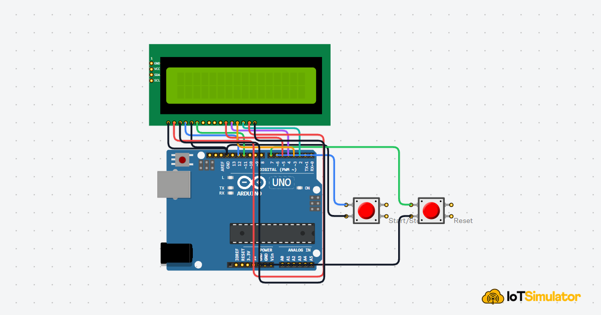
LCD Object Matches the Display Wires
The LCD1602 uses six Arduino pins in this project. The LiquidCrystal line tells the library exactly which pins connect to RS, E, D4, D5, D6, and D7 on the display.
If one of these pin numbers does not match the wiring, the LCD may show scrambled text or stay blank. That is why the display pins are grouped together near the top of the sketch.
Setup Prepares the Sensor, Display, and Buzzer
In setup(), the Arduino chooses which pins send signals and which pins listen. OUTPUT means the Arduino controls that pin. INPUT means the Arduino reads what another component sends to that pin.
lcd.begin(16, 2) tells the library that the display has 16 columns and 2 rows. The short startup message gives you quick feedback that the LCD is wired and responding.
Trigger Pulse Starts One Distance Measurement
The trigger section begins by writing LOW to the trigger pin for 5 microseconds. That gives the sensor a clean quiet moment before the real start pulse. Then the Arduino writes HIGH for 10 microseconds, which tells the HC-SR04 to send one ultrasonic burst.
After that, the pin goes back to LOW. This tiny HIGH pulse is like tapping a stopwatch. It starts one measurement, then the sketch waits for the echo response. The timing is very short, but the pattern is important because the sensor expects a clean start signal.
Echo Time Becomes Centimeters
pulseIn(echoPin, HIGH) measures how long the ECHO pin stays HIGH. That time is stored in echoTime. The next line converts that time into centimeters by multiplying by the speed of sound and dividing by 2.
The division by 2 is the important detail: the sound traveled to the object and back, but we only want the one-way distance from the sensor to the object.
LCD Refreshes the Live Distance
The LCD is only 16 characters wide on each row. If it first prints Distance: 100cm and later prints Distance: 9cm, leftover characters can remain on the screen unless the old text is removed. Clearing the display keeps the beginner version easy to understand.
In more polished projects, you can avoid flicker by printing spaces after shorter values instead of clearing the whole display. For this first version, lcd.clear() keeps the output simple and readable while you focus on the distance-to-warning idea.
Distance Zones Control the Buzzer
The if section compares the measured distance with two thresholds. An if statement is a decision: if the condition is true, that block of code runs. If it is false, the Arduino checks the next condition.
The stop zone is checked first because it is the most urgent. Anything at 10 cm or closer should produce a steady warning. The close warning comes second, between 10 cm and 25 cm, and creates a fast beep by turning the tone on briefly, stopping it, and pausing briefly. Anything farther away is treated as safe, so the buzzer stays quiet.
This is the same logic a real parking sensor uses in a simplified form. The exact hardware may be different, but the idea is the same: measure distance, choose a zone, then produce feedback that matches the risk.
Adjusting the Warning Distance
If the buzzer starts beeping when the object still feels far away, lower warningDistanceCm. If you want earlier warning, raise it. Start with small changes, like moving from 25 cm to 30 cm, then test again with your hand or a flat box in front of the sensor.
If the STOP warning starts too late, raise stopDistanceCm. A value of 15 cm gives more safety margin than 10 cm. The best value depends on the scale of the model you are building. A tabletop demo can use short distances, while a larger model car may need bigger numbers.
Keep the sensor pointed straight at the object while testing. Angled, soft, or very narrow surfaces may bounce the sound away instead of back to the receiver. When that happens, the reading can jump or become unreliable even when the wiring is correct.
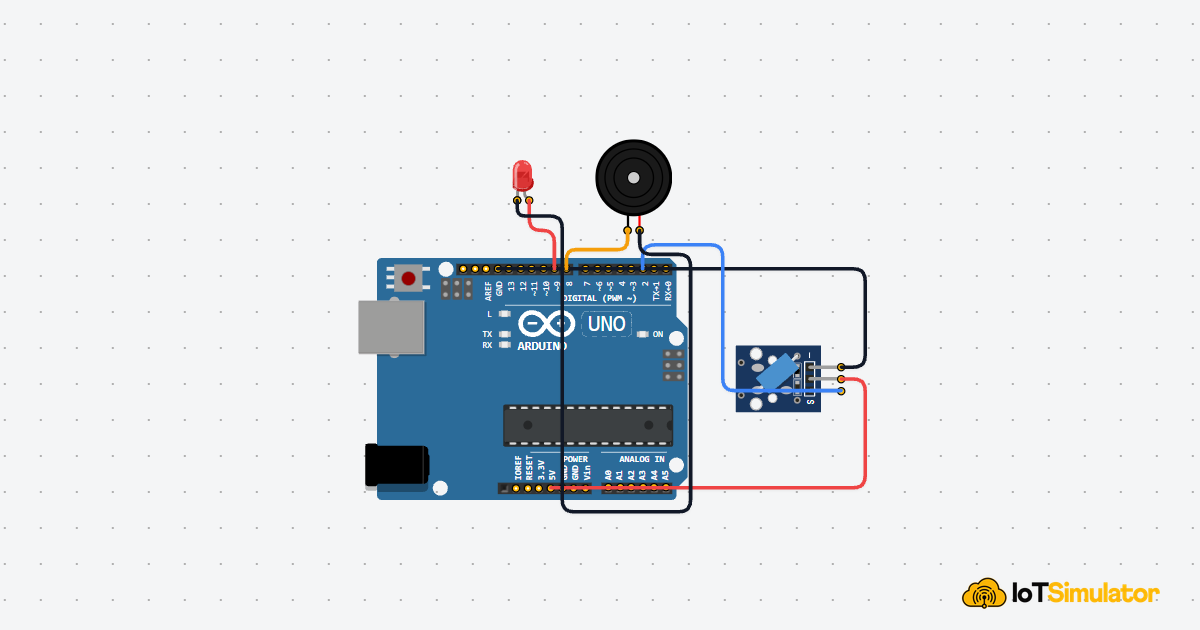
Taking It Further
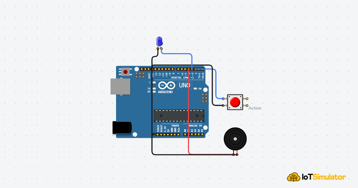
Once the basic alert works, the easiest upgrade is to add an LED that turns red in the stop zone and green in the safe zone. That gives the project both sound and visual feedback.
You can also change the distance zones for a different use. A robot obstacle alarm might warn at 40 cm instead of 25 cm. A small desk demo might warn at 15 cm. The important thing is that the same code structure still works: one distance reading, a few thresholds, and a clear output for each zone.