Build a 7-Segment Countdown with Arduino
Build a simple countdown timer with an Arduino Uno, a single-digit 7-segment display, a push button, and a buzzer. Press the button to count from 9 down to 0, then hear a short finish alert when the countdown ends.
Live project track
A countdown timer is easy to understand before we touch the code. Press a button, watch the number step down, and listen for a beep when the count reaches zero. That familiar flow makes this a strong beginner project because the goal is visible from the first second.
In this project, you will build a single-digit countdown timer with an Arduino Uno, a 7-segment display, a push button, and a buzzer. The main concept is: a number on a 7-segment display is really a pattern of smaller LED segments.
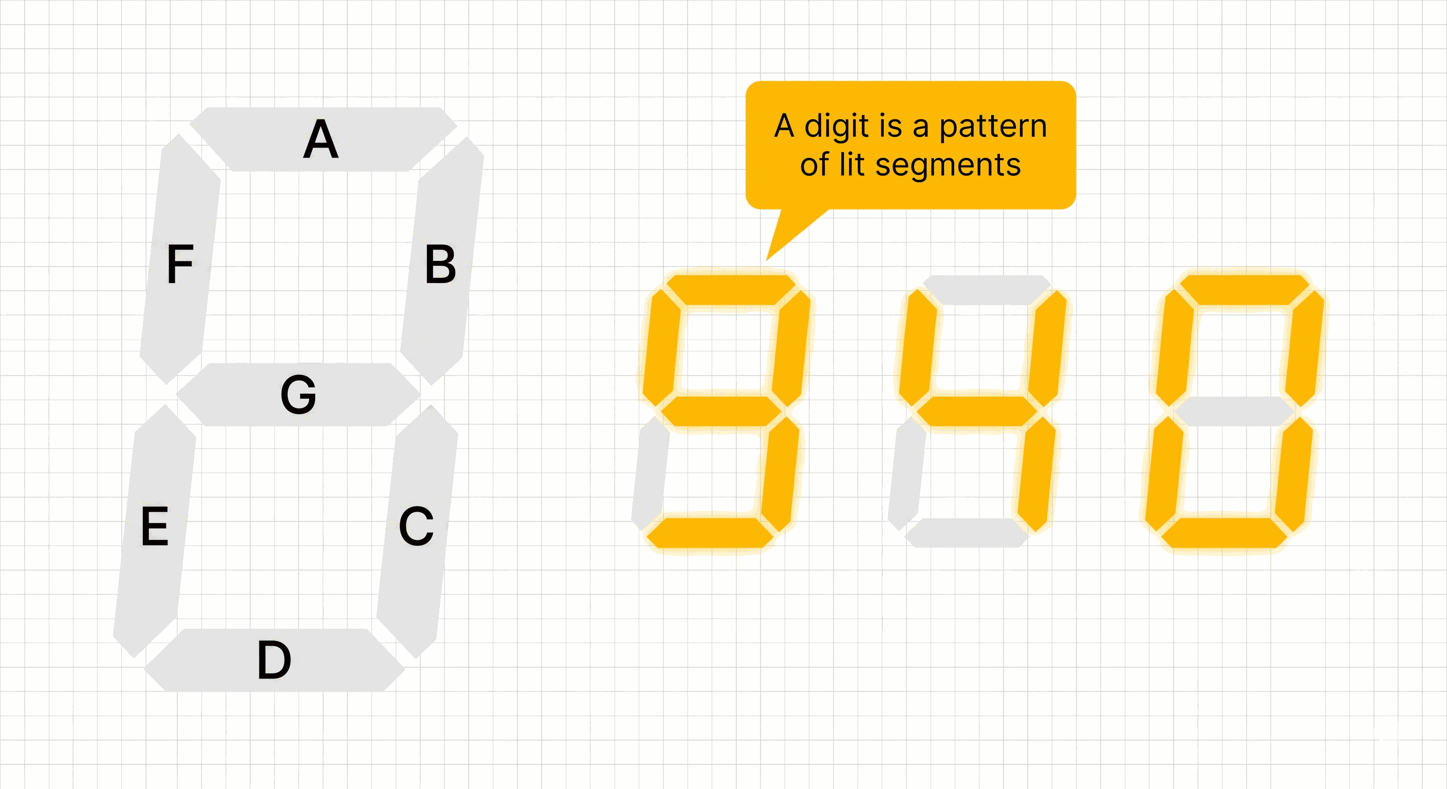
Each Countdown Number Is a Segment Pattern
A 7-segment display looks like one numeric display, but it is made from separate LED bars. Those bars are usually named A, B, C, D, E, F, and G. To show a number, the Arduino does not send the number directly. It turns on the exact bars that make that digit recognizable.
For example, the number 8 uses every segment. The number 1 only uses the two right-side segments. The number 0 uses almost everything except the middle segment. Once you see the display this way, the code becomes less mysterious: each digit is just an on/off recipe.
| Digit | Segments that turn on | Why it looks right |
|---|---|---|
| 9 | A, B, C, D, F, G | Everything except the lower-left segment |
| 1 | B, C | Only the two right-side bars |
| 0 | A, B, C, D, E, F | A full outline without the middle bar |
This is why the sketch is intentionally a little long. Instead of hiding the digit patterns inside an array or helper function, it writes the segment states directly. That makes the beginner lesson more visible: number equals pattern.
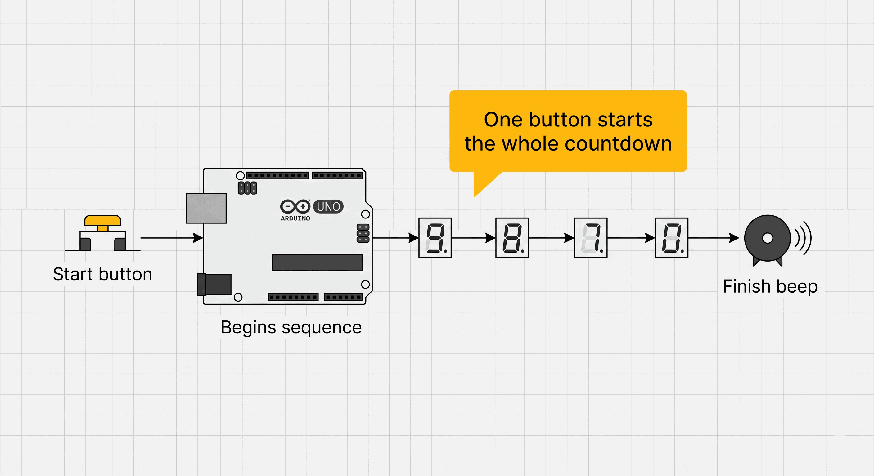
One Button Starts the Whole Countdown Sequence
The push button has one job: start the countdown from 9. After the button press, the Arduino handles the rest. It shows 9, waits one second, shows 8, waits again, and keeps going until the display reaches 0.
The code uses a small memory variable called counting. When counting is true, the countdown is active and the number should decrease. When counting is false, the display waits at zero and the buzzer stays quiet.
The button does not count down by itself. It only tells the Arduino to begin a sequence, and the Arduino updates the display one number at a time.
The button uses INPUT_PULLUP, which means the Arduino normally reads HIGH when the button is not pressed. When the button is pressed, it connects the pin to GND and the reading becomes LOW. GND is the return path for electricity, like the negative terminal of a battery.
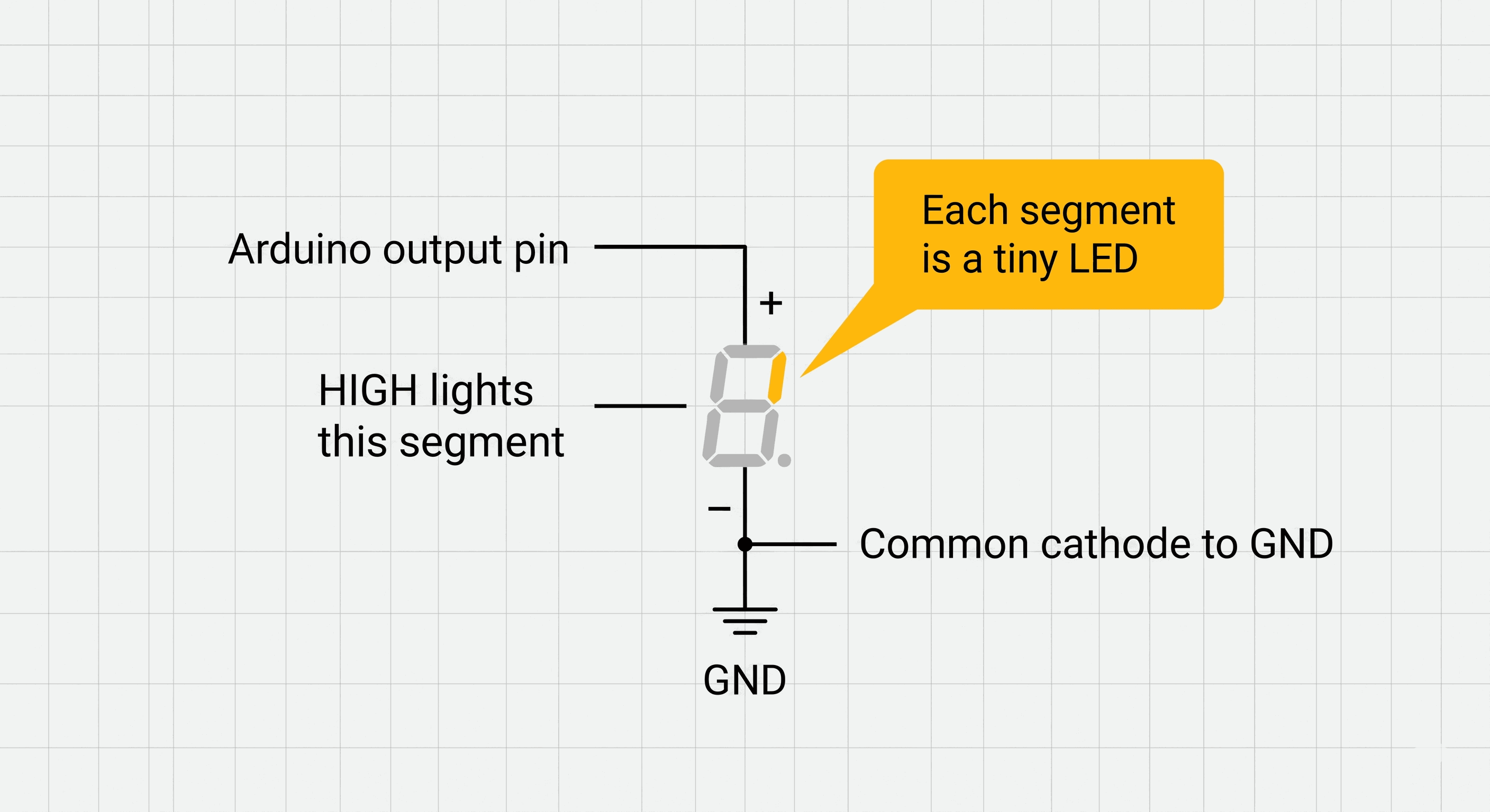
A Common Cathode Display Lights Segments With HIGH Signals
This project uses the display like a common cathode module. Common cathode means the shared COM pins connect to GND. With that setup, a segment turns on when its Arduino pin is set HIGH. HIGH means the pin is near 5V, so power can flow through that segment LED.
- COM pins connect the shared side of the display to GND.
- Segment pins connect to Arduino output pins.
- HIGH output lights a segment in this common cathode setup.
- LOW output turns that segment off.
Real 7-segment displays should use current-limiting resistors for the segments because each segment is an LED. The simulator keeps the wiring simple, but on a physical breadboard you should add resistors so the display and Arduino pins are protected.
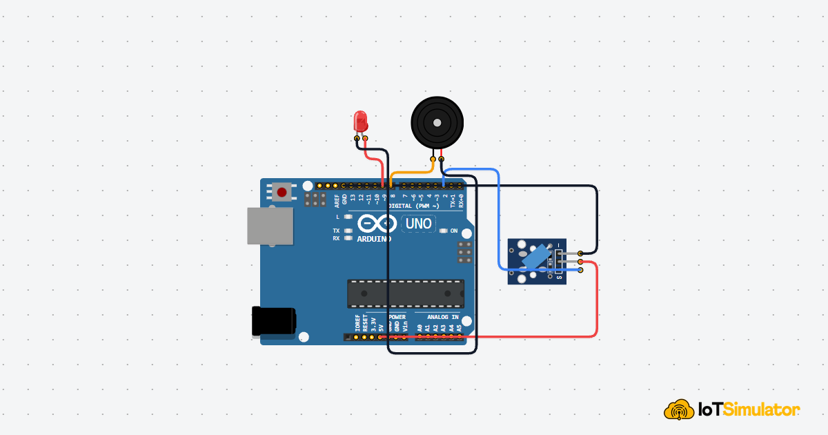
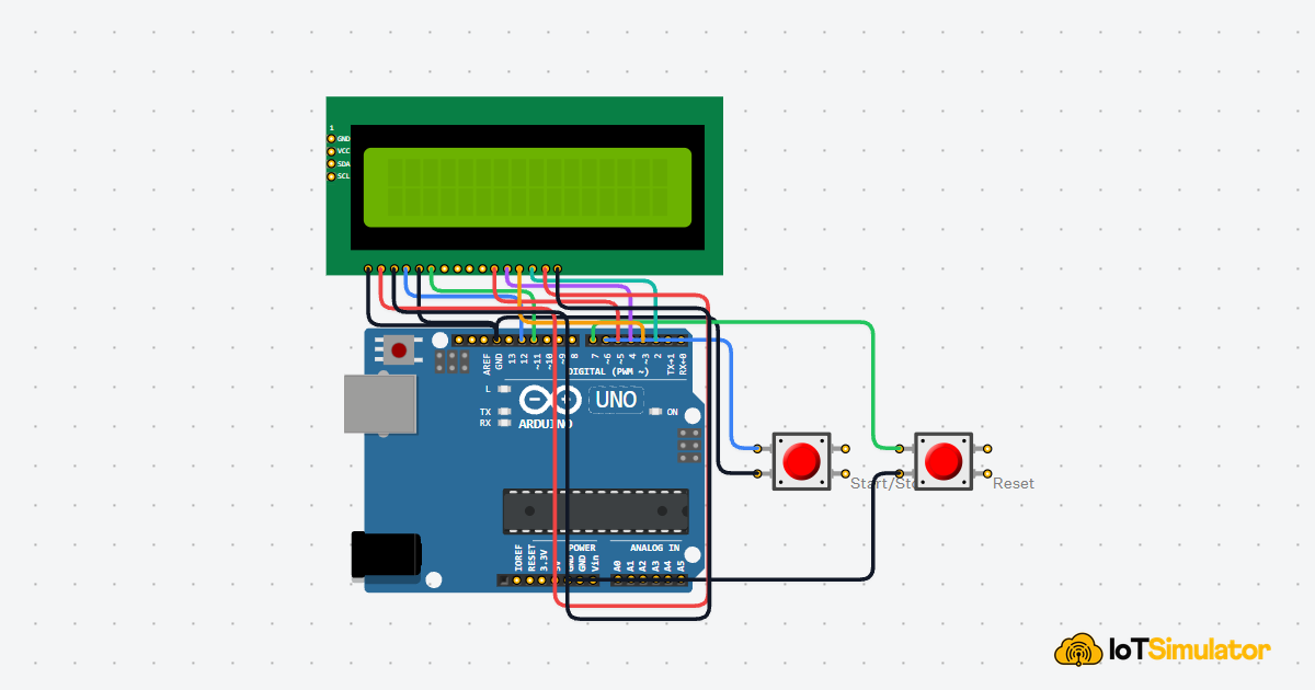
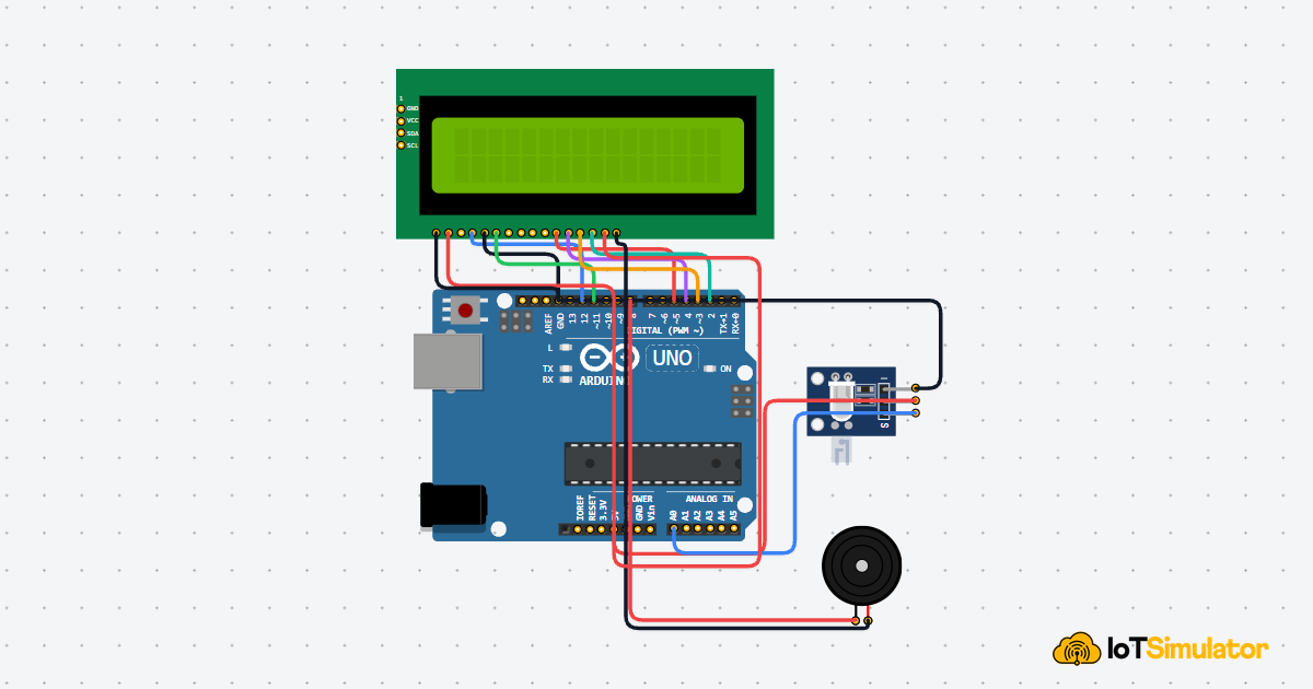
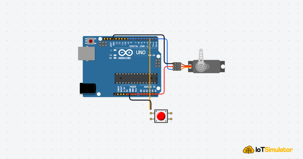
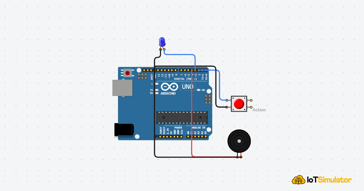
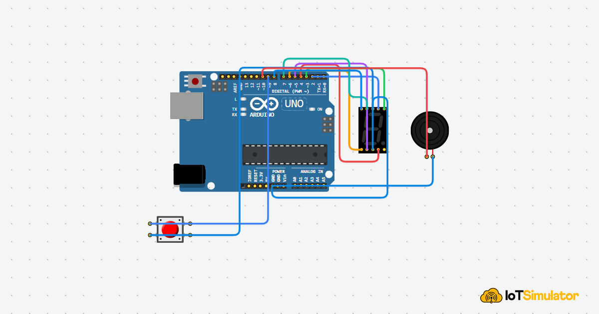
Each Wire Controls One Countdown Part
The circuit has three working groups. The 7-segment display shows the countdown number. The push button starts the sequence. The buzzer gives a finish alert when the display reaches zero.
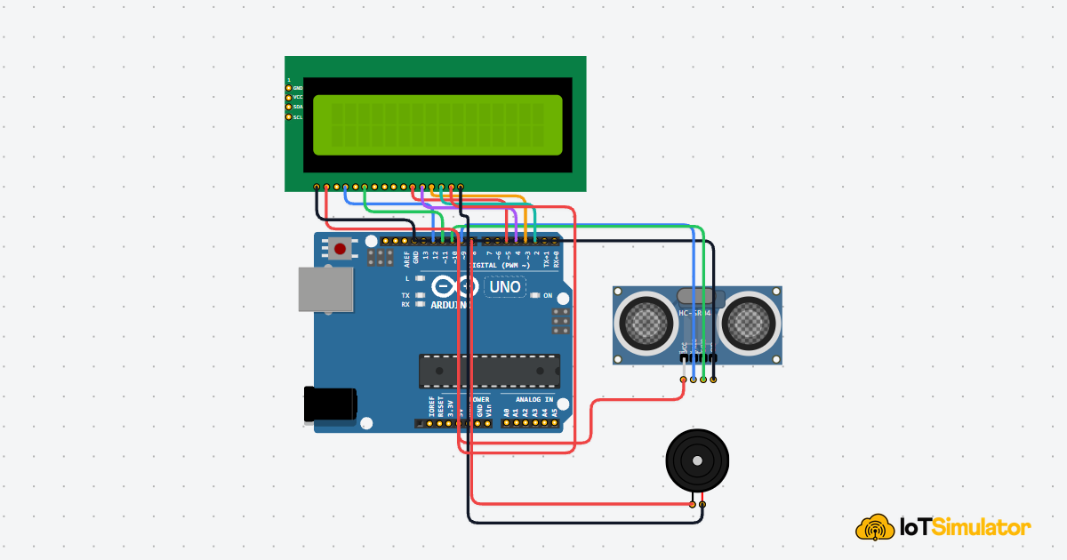
The display uses many wires because every segment is controlled separately. That is the main tradeoff of a single 7-segment display: the output is very clear, but the Arduino must control each LED bar.
Controls the top segment of the digit.
Controls the upper-right segment.
Controls the lower-right segment.
Controls the bottom segment.
Controls the lower-left segment.
Controls the upper-left segment.
Controls the middle segment.
Connects the common cathode side to ground.
Connects the second common pin to the same ground reference.
Carries the start button signal into the Arduino.
Pulls D9 LOW when the button is pressed.
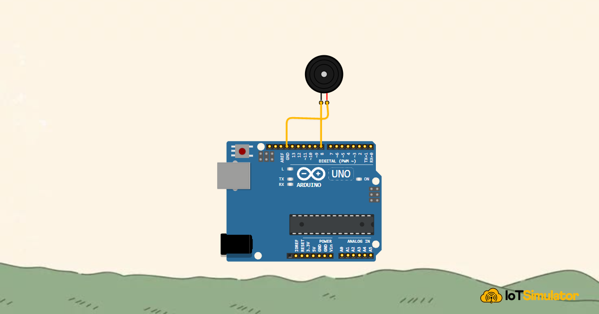
Receives the finish tone signal.
Completes the buzzer circuit back to ground.
If the display lights the wrong shape, check the segment wires first. A swapped B and C wire can make the countdown numbers look strange even when the code is correct.
The Complete 7-Segment Countdown Sketch
The sketch is longer than many beginner examples because it writes each segment directly. That is a conscious choice for learning. A shorter version could use arrays or helper functions, but this version keeps every segment decision visible.
The countdown starts when the button is pressed. The display updates once per second, and the buzzer plays a short tone after zero.
How the 7-Segment Countdown Code Works, Part By Part
Now let us break the sketch into smaller pieces. The code has four main jobs: name the pins, start the countdown, draw the current digit, and beep when the countdown reaches zero.
▸ Countdown Segment Pins Name Each LED Bar
The first lines name each display segment. Pin numbers are the physical Arduino connectors used by the wires. Naming the pins makes the code read like a wiring diagram.
▸ Setup Prepares Display, Button, and Buzzer
In setup(), every segment pin becomes an OUTPUT, which means the Arduino controls that pin. The button uses INPUT_PULLUP, so it normally reads HIGH and reads LOW when pressed. The buzzer pin is also an output because the Arduino sends the finish tone.
▸ Button Loads 9 as the Starting Number
When the button reads LOW, the countdown starts. The sketch sets counting to true and loads currentNumber with 9. The short pause keeps one tap from being read again immediately.
▸ Digit Blocks Light the Right Segments
The long if and else if section chooses which segment pins turn on for the current number. For digit 9, segment E is off and the other main segments are on. For digit 1, only B and C are on.
The full sketch includes all digits from 0 to 9. It is verbose, but it lets beginners see the exact relationship between a number and the segments that form it.
▸ Running Mode Steps Toward Zero
If counting is true, the Arduino waits one second. If the current number is not zero, it subtracts one. That repeated subtracting is what turns the display into a countdown.
When the number reaches zero, the buzzer plays a short finish tone and counting becomes false. The display stays at zero until the button starts a new countdown.
Adjusting the Countdown Timing and Alert
If you want the countdown to move faster, reduce countdownDelayMs. A value of 500 makes each digit last half a second. If you want a slower timer, increase it to 1500 or 2000.
The buzzer finish alert is controlled by finishToneHz and finishBeepMs. Lower the frequency for a deeper beep, raise it for a sharper beep, and change the duration if the alert feels too short or too long.
Taking It Further
Once the countdown works, you can add a second button that resets the timer immediately. You can also connect the decimal point and blink it during the countdown as a small activity indicator.
A later version can use arrays or helper functions to make the digit patterns shorter. That is a good next step after the beginner version makes the segment logic clear.