Display Heartbeat BPM on an Arduino LCD
Build an Arduino heartbeat monitor with a pulse-style heart beat sensor, an LCD1602 display, and a buzzer. The Arduino watches the analog pulse signal, detects clean beat peaks, estimates BPM from the time between beats, and shows the live result on the LCD.
Live project track
Have you ever felt your pulse on your wrist and counted the beats for a few seconds? You are doing two things at once: noticing each beat and measuring the time between them. A heartbeat monitor does the same basic job, but it lets the Arduino do the counting and timing.
In this project, a heart beat sensor gives the Arduino a changing analog signal. The Arduino watches for clean peaks in that signal, estimates beats per minute, shows the result on an LCD1602 display, and makes a short buzzer beep when a beat is detected. The one main concept is: BPM comes from the time between repeated beat peaks, not from one single sensor reading.
This is a learning project, not a medical device. Use it to understand sensors, signals, and timing, not to make health decisions.
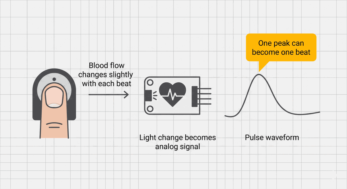
Blood Flow Changes Become a Pulse Waveform
Think of the sensor like a tiny flashlight and observer looking at your fingertip. With each heartbeat, blood flow in the finger changes slightly. That small change affects how much light is reflected or absorbed. The sensor turns that changing light level into an electrical signal.
The Arduino does not see a neat number called heartbeat. It sees an analog value that rises and falls. Analog means the value can move through a range, like 512, 548, 601, and back down again, instead of only being on or off. The peak of that rise is the clue we use to detect one beat.
| What happens physically | What the Arduino receives | What the code does |
|---|---|---|
| Blood flow changes with a beat | The sensor value rises | Watch for the value crossing a threshold |
| The beat passes | The sensor value falls again | Wait until the signal is ready for another beat |
| Beats repeat over time | Peaks appear again and again | Measure the time between peaks |
This is why heartbeat projects can feel a little more delicate than a button project. A button usually gives a clear HIGH or LOW. A pulse sensor gives a shape. The code has to decide which part of that shape counts as a real beat and which part is just noise.
Two Thresholds Stop One Beat From Being Counted Twice
If the code counted a beat every time the signal was above one threshold, one real heartbeat could be counted many times. The Arduino loop runs very fast, so the signal might stay above the threshold for several loop cycles. That would make the BPM jump unrealistically high.
To prevent that, this project uses two thresholds. The higher beatThreshold detects the beat peak. The lower releaseThreshold tells the Arduino when the waveform has fallen enough to be ready for the next beat. This gap is called hysteresis. In plain words, the signal must rise high enough to count, then fall low enough before it can count again.
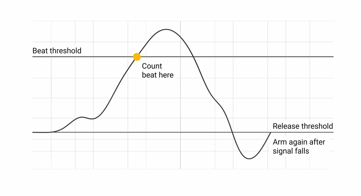
- Beat threshold is the upper line that marks a likely heartbeat peak.
- Release threshold is the lower line that re-arms the detector after the signal falls.
- Ready for beat is the code's memory that prevents one long peak from being counted repeatedly.
If the buzzer chatters rapidly, the threshold is probably too low or the signal is noisy. Raise beatThreshold or steady the sensor contact before changing the rest of the code.The Gap Between Peaks Becomes BPM
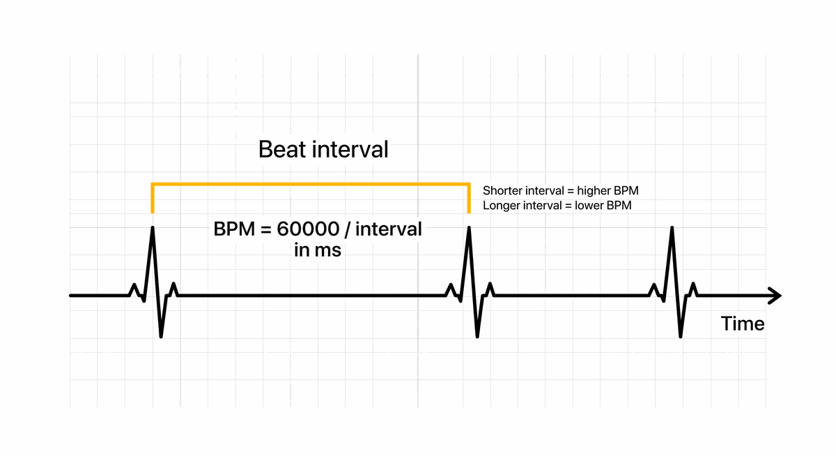
BPM means beats per minute. The Arduino does not need to wait one full minute to estimate it. Instead, it measures the time between two neighboring beats and scales that interval up to one minute.
If two beats are 1000 milliseconds apart, that is one beat per second. One beat per second becomes 60 beats per minute. If the interval is 500 milliseconds, that is two beats per second, or 120 BPM. The formula in the code is 60000 / interval because there are 60,000 milliseconds in one minute.
| Beat interval | Estimated BPM | Meaning in the project |
|---|---|---|
| 1000 ms | 60 BPM | One beat every second |
| 750 ms | 80 BPM | Faster than one beat per second |
| 500 ms | 120 BPM | Two beats every second |
The sketch also rejects intervals that are too short or too long. A beat interval under 300 milliseconds would imply more than 200 BPM, which is usually a false trigger in this learning setup. A gap longer than 2000 milliseconds is treated as too old to produce a useful live BPM estimate.
Steady Contact Makes the BPM Reading Less Jumpy
Pulse sensors are sensitive to movement. If the fingertip slides, presses too hard, or barely touches the sensor, the waveform can become jagged. The Arduino may then see fake peaks and count them as beats. This is why heartbeat projects often need more patience than light or temperature projects.
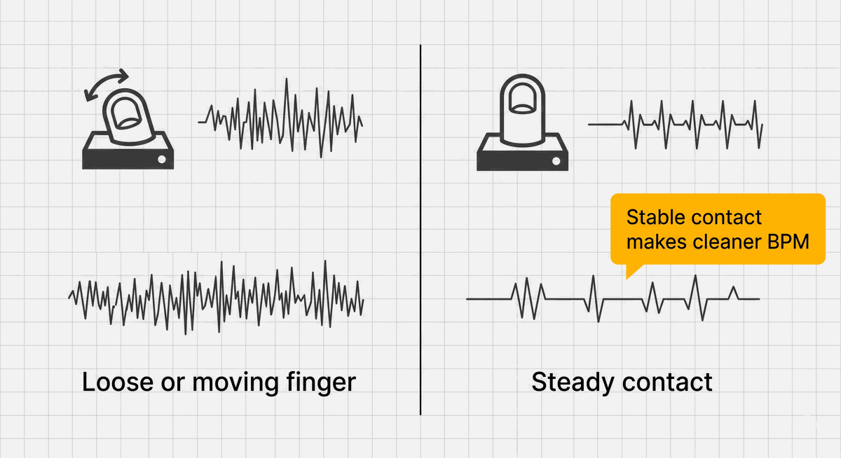
For the cleanest result, hold the sensor still and give the reading a few seconds to settle. In the simulator, you can use the pulse control to test different signal levels. On a real sensor, the first debugging step is usually not code. It is better contact, less movement, and less strong light hitting the sensor.
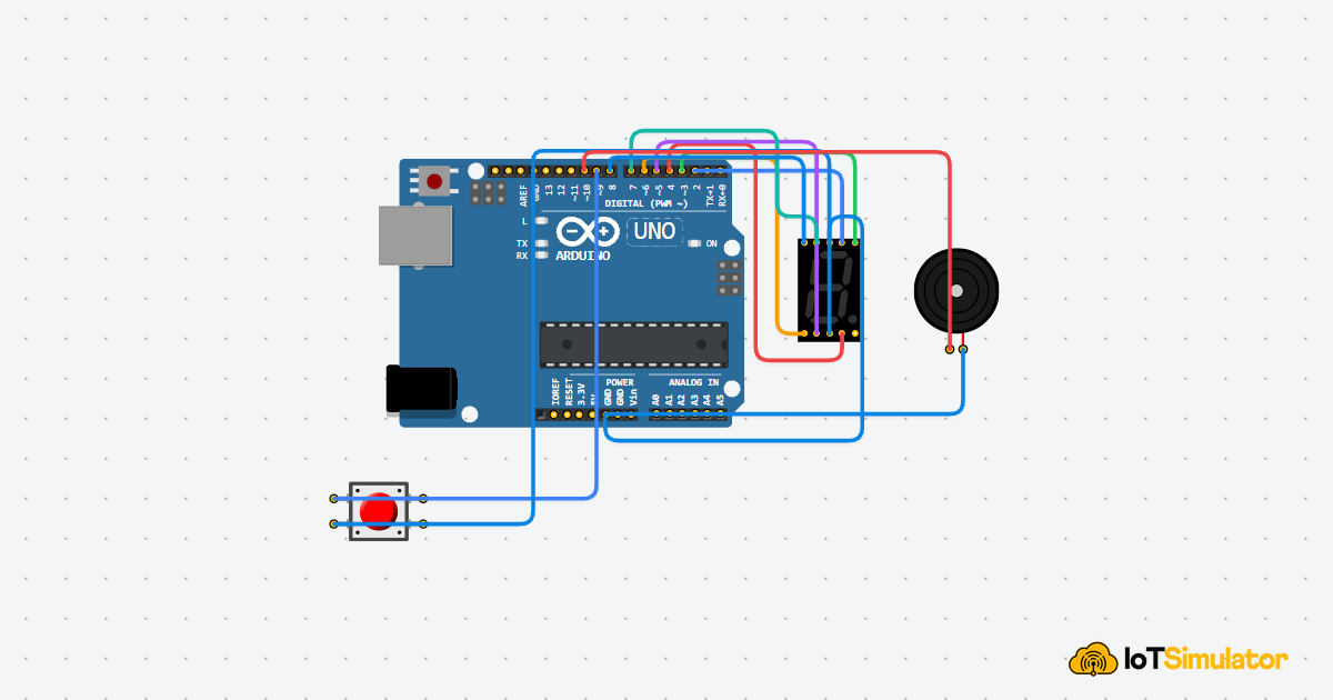
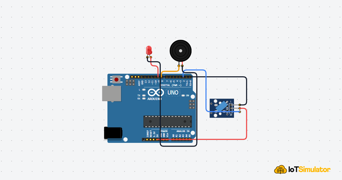
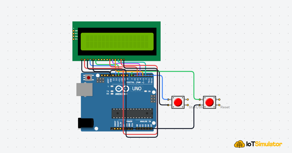
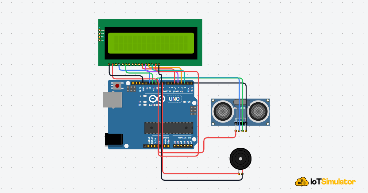
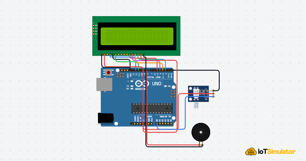
Each Heartbeat Monitor Wire Has One Simple Role
The circuit has three groups: the pulse sensor reads the body signal, the LCD shows the BPM and raw signal, and the buzzer gives a short beep for each detected beat. The Arduino sits in the middle and makes the timing decision.
5V is the positive power supply from the Arduino. GND is the return path for electricity, like the negative terminal of a battery. The sensor, LCD, and buzzer all need a shared GND so their signals use the same zero-voltage reference.
Powers the light-sensing circuit inside the pulse module.
Shares the same return path and voltage reference as the Arduino.
Sends the changing analog pulse signal into the Arduino.
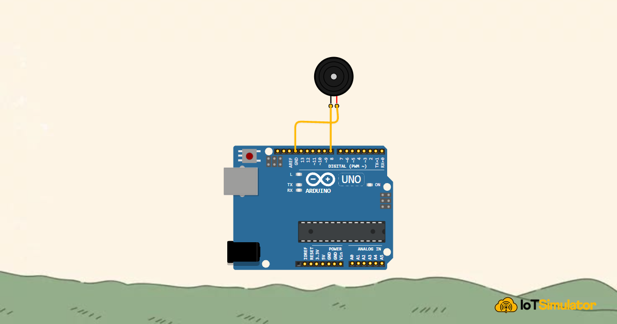
Receives the short tone signal when a beat is detected.
Completes the buzzer circuit back to ground.
Ground for the LCD logic.
Power for the LCD logic.
Keeps the LCD in write mode so Arduino sends text to it.
Chooses whether the LCD receives a command or display text.
Tells the LCD to accept the current data.
First data line used by the display in 4-bit mode.
Second data line used by the display in 4-bit mode.
Third data line used by the display in 4-bit mode.
Fourth data line used by the display in 4-bit mode.
Power for the LCD backlight.
Ground for the LCD backlight.
If the LCD works but BPM stays as --, check the raw signal number on row 2. If it never rises above the beat threshold, the sensor signal is too low or the threshold is too high.The Complete Heartbeat BPM Monitor Sketch
This sketch uses timing logic, so it is more advanced than a basic LED project. The key idea is still understandable: sample the pulse sensor, count only clean peaks, measure the time between peaks, and update the LCD.
The code uses millis() instead of only delay() because the buzzer beep should end while the sensor keeps being checked. millis() returns how many milliseconds have passed since the Arduino started running, which makes it useful for timing events without stopping the whole sketch.
How the Heartbeat BPM Code Works, Part By Part
Now let us break the sketch into smaller jobs. Each block supports one part of the monitor: sensor input, peak detection, beat timing, buzzer feedback, and LCD display.
▸ Heartbeat Monitor Pins and Thresholds Define the Signal Rules
The first constants name the sensor pin, buzzer pin, LCD pins, and detection values. A constant is a named value that does not change while the program runs. Using names keeps the project readable because beatThreshold explains itself better than a mystery number like 560.
The threshold pair is the most important setting to tune. If real beats are missed, lower beatThreshold a little. If fake beats are counted, raise it or increase the gap between the beat and release thresholds.
▸ Monitor Memory Prevents Repeat Counting
The variables remember the state of the monitor between loop cycles. readyForBeat tells the sketch whether the next high signal is allowed to count as a new beat. The time variables remember when the last beat, beep, and display update happened.
▸ Setup Starts the LCD Before Reading
The setup section prepares the buzzer as an OUTPUT, which means the Arduino sends a signal from that pin. Then it starts the LCD and prints a short message so the reader sees that the display is responding before the BPM value appears.
▸ Loop Samples the Pulse Waveform
Each loop reads the analog sensor signal from A0. analogRead() returns a number from 0 to 1023, where higher numbers mean a higher input voltage. The sketch also stores the current time from millis() so every timing decision uses the same time reference.
▸ Threshold Crossing Counts One Beat
The beat detector only runs when two things are true: the monitor is ready for a beat, and the signal is above the beat threshold. After counting that peak, the code sets readyForBeat to false so the same high pulse cannot be counted again.
The second if statement re-arms the detector only after the signal falls below the release threshold. That fall is what tells the Arduino that the previous beat has passed.
▸ Interval Math Updates the BPM
handleBeat() measures the gap between this beat and the previous beat. If the interval looks realistic, the code divides 60,000 by that interval to estimate BPM. The UL in 60000UL tells Arduino to treat the number as an unsigned long value, which is safer for time math.
▸ Short Beep Confirms the Detected Peak
The buzzer starts when a beat is detected, but it should not stay on forever. The sketch stores lastBeepStart, then later turns the tone off when beepDurationMs has passed. This gives each beat a quick audible tick without blocking sensor reading for too long.
▸ LCD Shows BPM and Raw Signal
The LCD shows the estimated BPM on the first row and the raw sensor signal on the second row. The raw signal is included on purpose. It helps learners tune the threshold because they can see whether the sensor value is rising above the detection line.
Adjusting the Heartbeat Threshold For Your Sensor
If the BPM never appears, watch the raw signal on the LCD. If the signal peaks around 535, the default threshold of 560 is too high for that setup. Lower it in small steps, such as 560 to 545, then test again.
If the BPM appears but jumps wildly, the threshold may be too low or the sensor contact may be moving. Raise beatThreshold, keep releaseThreshold lower than it, and hold the sensor more steadily. The best result usually comes from both better placement and a threshold that matches the observed signal.
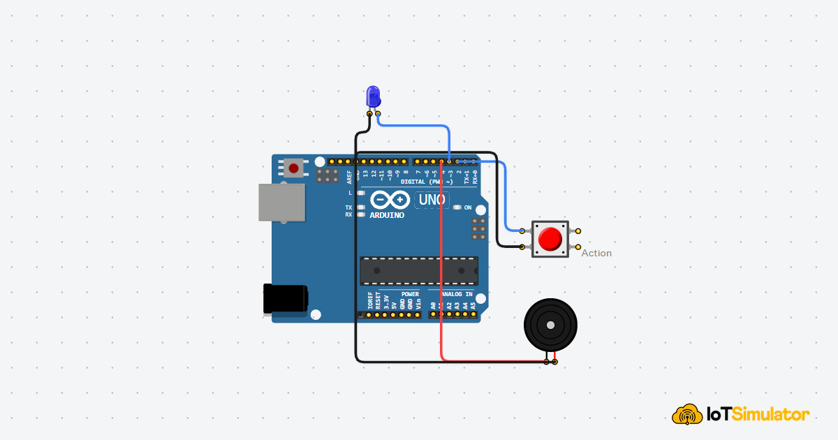
Taking It Further
Once the BPM display works, you can add an LED that flashes with the buzzer so each detected beat has both visual and audio feedback. You could also store the last few BPM values and display an average to make the reading less jumpy.
For a more polished version, try showing a warning when the signal stays too low for several seconds. That would teach the user to adjust their finger instead of trusting a blank or unstable BPM value.