Build a Servo Door Lock with Arduino
Connect a servo motor and a push button to your Arduino. Each press toggles the lock between open (0°) and closed (90°). This project introduces the most important thing a servo can do: move to a specific angle and stay there.
Live project track
Think about a door lock in real life. When you turn the key one way, a bolt slides out and blocks the door. Turn it the other way, the bolt slides back in. The door is either locked or unlocked — and it stays in whichever state you left it.
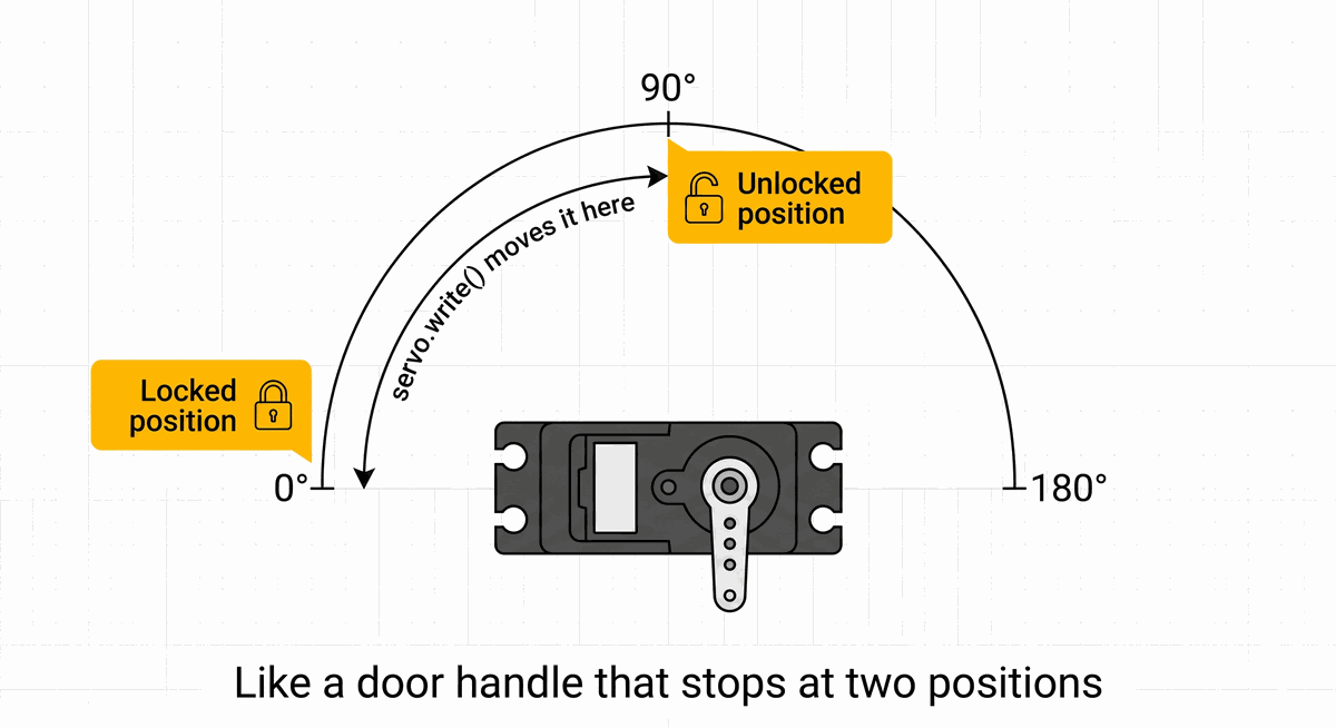
In this project, a servo motor is that bolt. It moves to one position to lock, and a different position to unlock. Press a button to switch between them. That is the whole project — and the single idea it teaches you is this: a servo does not just spin, it moves to a specific angle and holds it there.
Why a Servo Is Different From a Regular Motor
A regular motor spins continuously as long as power is applied — like a fan blade. You cannot easily tell it to stop exactly halfway. A servo is different. Inside every servo is a small brain that reads the command you send and physically rotates the output shaft to match that exact angle — then holds it there.
In code, you send one number: the angle in degrees. Send 0 and the servo rotates all the way to one side. Send 90 and it moves to the middle. Send 180 and it reaches the other end. The servo does the rest — it figures out how to get there and stays in that position even if something pushes against it.
What INPUT_PULLUP Means — and Why the Button Reads Backwards
When you set a pin to INPUT_PULLUP, the Arduino turns on a tiny resistor inside itself that connects the pin to 5V. This keeps the reading stable at HIGH (which means 5V — power is present) when the button is not pressed.
When you press the button, it connects the pin directly to GND — the 0V side. That pulls the reading down to LOW. So LOW means pressed, and HIGH means not pressed. This feels backwards at first, but it is the standard way Arduino buttons are wired because it needs no extra components — the Arduino provides the resistor itself.
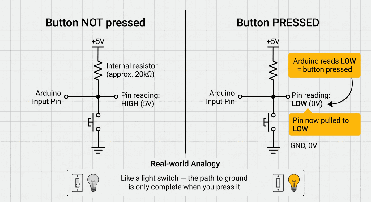
GND is the return path for electricity — think of it as the negative terminal of a battery. When the button connects the pin to GND, it gives electricity a complete path to flow, which changes the reading from HIGH to LOW.
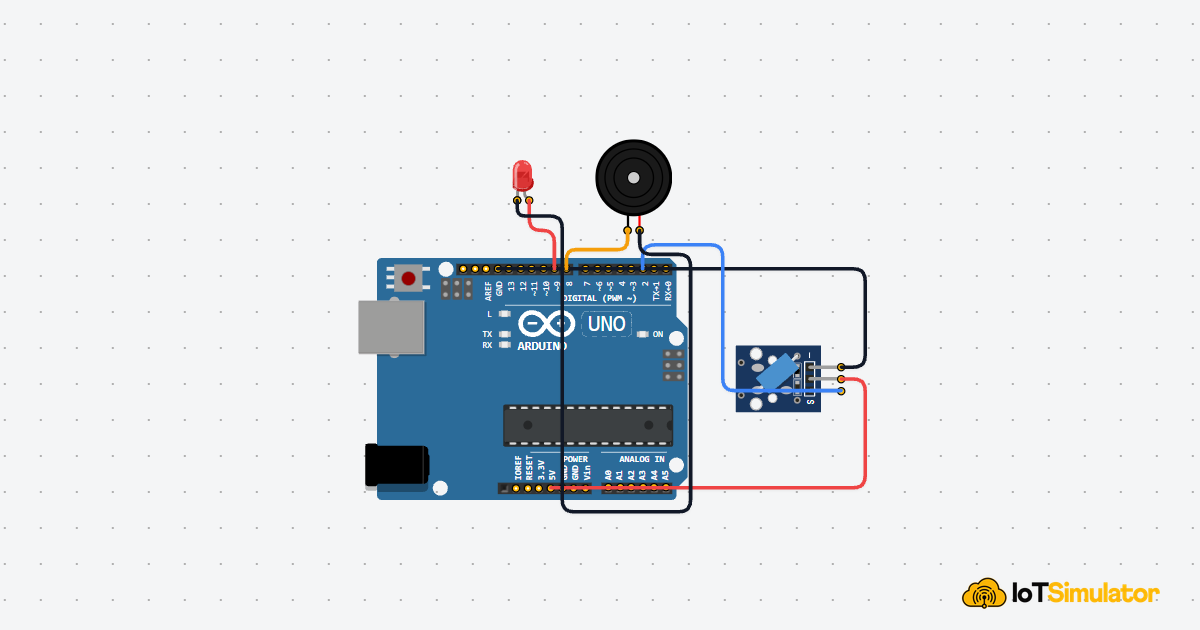
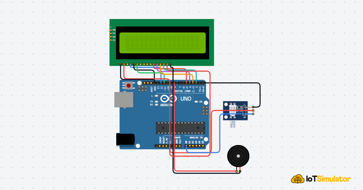
Wiring the Servo and Button
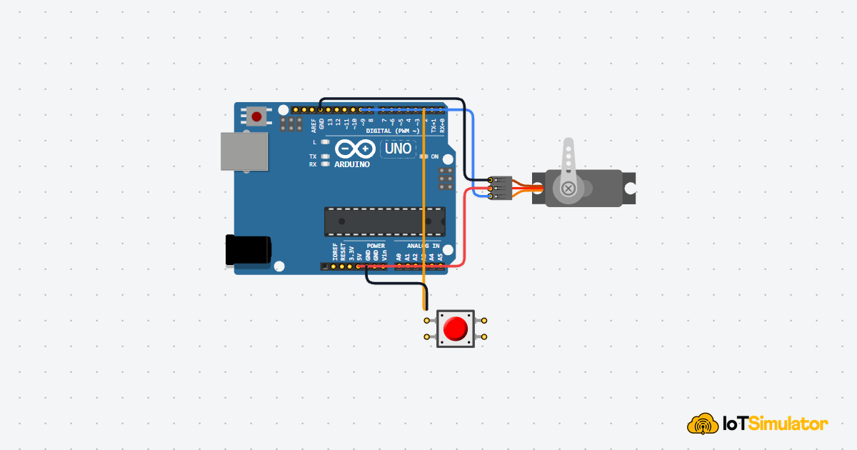
The servo has three wires. The power and ground wires keep the motor running. The signal wire is how the Arduino tells it which angle to go to. The button has two legs — one connects to an Arduino pin, the other connects to GND.
Carries the angle command from the Arduino to the servo.
Powers the servo motor. 5V is the positive power supply on the Arduino.
The return path for electricity — shared with the Arduino.
The Arduino reads this pin to know if the button is pressed.
When pressed, the button connects D2 to GND, changing the reading to LOW.
Servo wire colors are usually: orange or yellow = signal, red = power, brown or black = ground. These can vary by brand — always check your servo's datasheet if unsure.
How the Arduino Remembers the Lock State
Each time you press the button, the project needs to know whether it is currently locked or unlocked — so it can switch to the opposite state. To remember this between button presses, the code uses a variable called isLocked. A variable is like a sticky note that the Arduino keeps in memory while it is powered on.
When isLocked is true, the servo holds at 0° (locked). When it is false, the servo holds at 90° (unlocked). Every button press flips the value and the servo moves to match.
What the ! Does to isLocked
The line isLocked = !isLocked flips the value of the variable. If it was true, it becomes false. If it was false, it becomes true. The ! symbol in code means "the opposite of." It is like flipping a light switch — whatever state it was in, it goes to the other one.
Why the delay(300) Prevents Double Presses
After toggling the lock, the code waits 300 milliseconds before the loop reads the button again. Without this pause, a single press of your finger — which lasts around 100”“200ms — would be detected many times in a row because the loop runs thousands of times per second. The result would be the servo flickering back and forth instead of cleanly switching once. The delay acts as a simple waiting room that gives your finger time to lift off.
Taking It Further
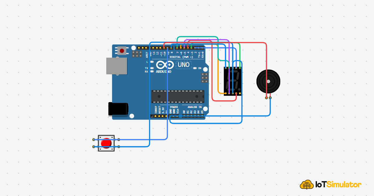
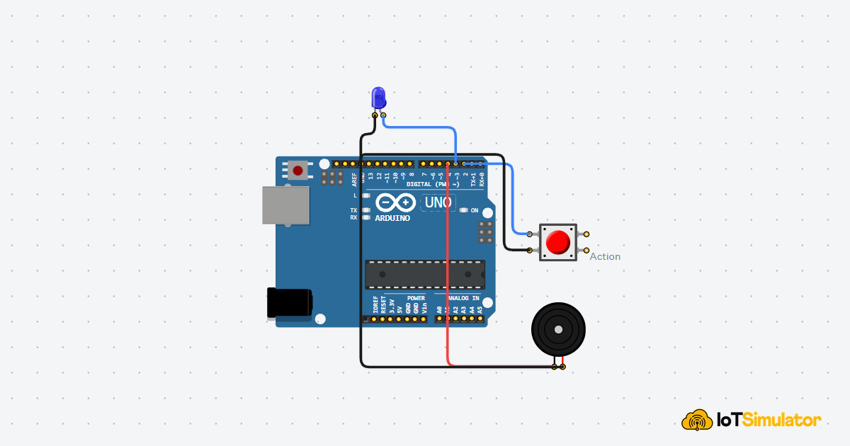
- Add a red LED that turns on when locked and a green LED that turns on when unlocked — a visual indicator of the current state.
- Add a buzzer that plays one short beep when locking and two beeps when unlocking, so you can hear the state change without looking at the device.
- Change
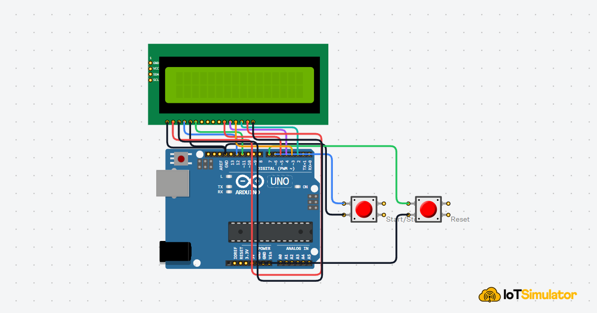
lockedAngleandunlockedAngleto match whatever physical mechanism you attach to the servo horn — some locks may need 45° instead of 90°. - Add a second button so one button always locks and the other always unlocks — instead of using a toggle.