If Arduino feels like a small robot brain, the ESP32-C3 is that same idea plus a Wi-Fi radio. It can still read sensors and drive LEDs, but it can also connect to your network for dashboards, web pages, or simple phone control.
This guide is the beginner-friendly overview: what the ESP32-C3 DevKit is, what the important pins mean, which pins to be careful with at boot, and a tiny first sketch you can run right away.
Description
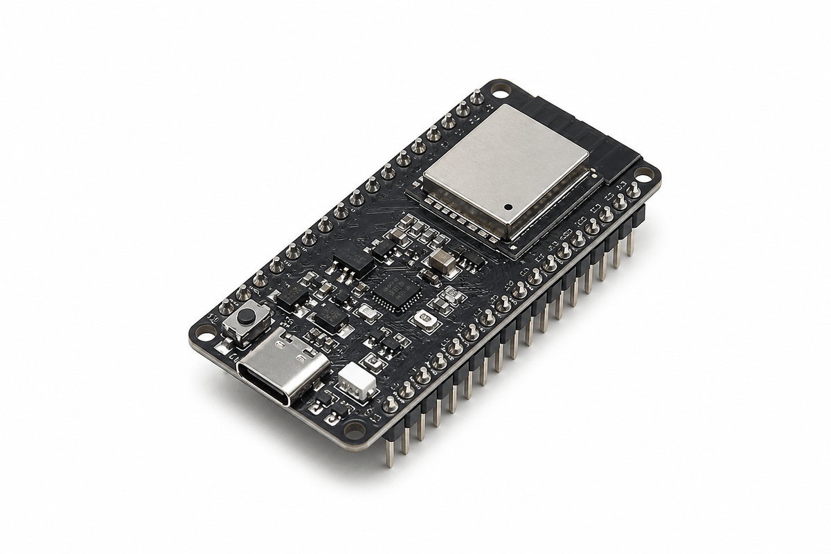
The ESP32-C3 DevKitM-1 is a small development board built around the ESP32-C3 chip and an ESP32-C3-MINI-1 module. The ESP32-C3 family combines a single-core RISC-V CPU with 2.4 GHz Wi-Fi and Bluetooth LE, which is why it shows up in a lot of beginner IoT projects.
One important beginner detail: the ESP32-C3 uses 3.3V logic. That means its GPIO pins are meant for 3.3V signals, not 5V. Many Arduino modules are 5V-friendly, so this is the first place people get surprised when moving from Uno to ESP.
Features
| Feature | What it means |
|---|---|
| Wi-Fi + Bluetooth LE | You can build wireless projects without extra shields. |
| 3.0V-3.6V supply (3.3V typical) | The chip is designed around 3.3V power and signals. |
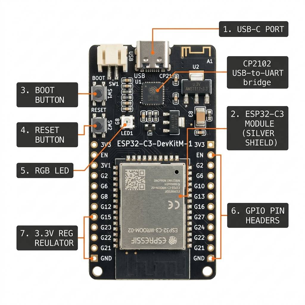
| BOOT + RESET buttons | Helps you enter download mode and restart quickly. |
| Strapping pins (GPIO2 / GPIO8 / GPIO9) | These pins are checked during reset - avoid wiring that pulls them the wrong way. |
| ADC (analog input) | Great for knobs and sensors, but note the ADC input range depends on attenuation. |
| WS2812 RGB LED on GPIO8 | The DevKitM-1 includes an addressable RGB LED driven by GPIO8. |
The BOOT button is used to enter firmware download mode. On the ESP32-C3 DevKitM-1, holding BOOT and pressing RESET puts the board into download mode.
Pin Basics (What Beginners Actually Use)
Power Pins
- 3V3: 3.3V supply rail for sensors that support 3.3V.
- 5V: 5V from USB (useful for powering 5V modules, but do not feed 5V into GPIO).
- GND: ground (the reference line - everything must share this).
- EN: reset/enable pin (RESET button toggles this).
GPIO Pins to Be Careful With
GPIO2, GPIO8, and GPIO9 are strapping pins on ESP32-C3 boards. That means their level during reset affects how the chip boots. For a first project, avoid wiring parts that might pull these pins LOW during reset (for example, a button to ground or a sensor output with a strong pull-down).
ADC Voltage Range (Quick Note)
The ESP32-C3 ADC can measure analog voltage, but the usable range depends on the attenuation setting. In ESP-IDF docs, the widest listed range reaches up to about 2.5V with 11 dB attenuation. So if you connect a sensor that outputs 0-3.3V, you may need a divider or choose the right attenuation in firmware.
Wiring Tips
- Always share ground: if your sensor and board do not share GND, readings will look random or stop working.
- 3.3V signals only: if a module outputs 5V logic, use a level shifter (or a resistor divider for simple one-way signals).
- Start with one LED: it's the fastest way to confirm a GPIO pin is doing what you think.
Simple Demo: Blink an LED (Through a Resistor)
GPIO2 toggles HIGH/LOW to blink the LED.
Completes the circuit back to ground so current can flow.
A safe first wiring: IO2 drives an LED through a resistor.

Use the code below (shown on this page) to blink that LED. If it does not blink, double check the LED direction: the anode (A) must be on the resistor side, and the cathode (C) must go to GND.
Wrapping Up
The ESP32-C3 DevKit is a great next step after Arduino because it keeps the same simple GPIO workflow while adding wireless features.
If you remember only two things: (1) it is a 3.3V board, and (2) be careful with strapping pins (GPIO2/8/9) when you wire your first circuits. With that, you can build reliable beginner projects and grow into Wi-Fi dashboards later.