This article is a guide about the ILI9341. We will explain how it works, show how it is wired, and walk through an Arduino example you can use in your own projects.
The ILI9341 becomes useful when you want the screen to do more than print one line of text. It can show menus, colored status blocks, sensor values, and small graphics, which makes the whole project feel more like a proper interface.
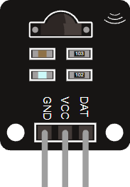
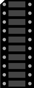
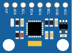
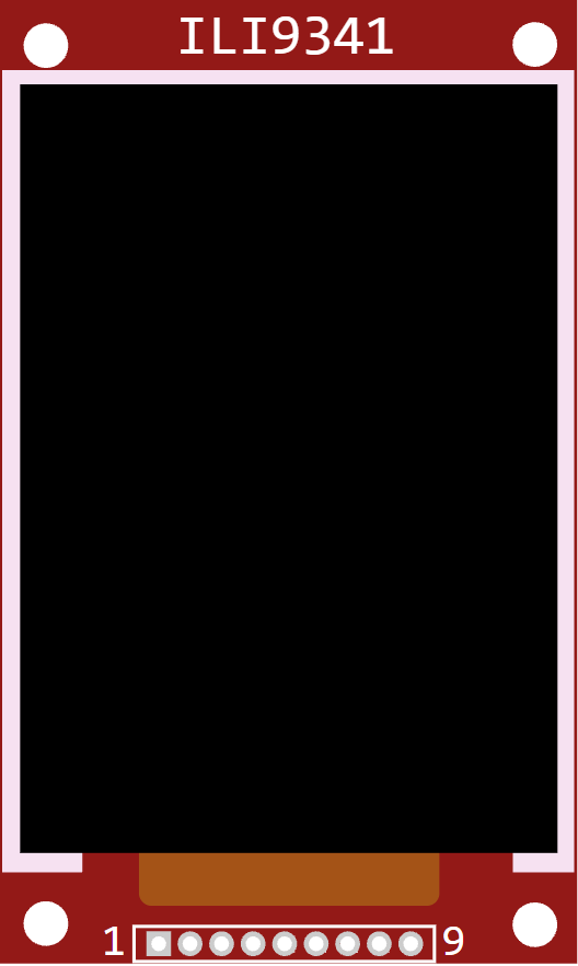
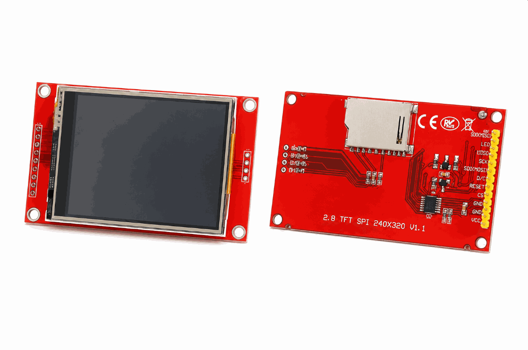
Before we jump into the wiring, it helps to look at the real module first so the screen size, header pins, and backlight area are easier to recognize.
Description
The ILI9341 is a color TFT display controller used in 240x320 pixel screens. It can draw text, shapes, images, and UI elements, so it is much more flexible than a character LCD when you want a colorful interface.
That makes it a strong choice for dashboards, touch-style interfaces, sensor visualizations, and beginner projects that need something more lively than a black-and-white screen. The display is small enough for embedded projects but rich enough to feel like a tiny screen instead of a simple output lamp.
The simulator version follows the same basic idea you would use on real hardware: a microcontroller sends commands and pixel data over SPI, and the display turns that data into visible color on the screen.
TFT vs Common LCD
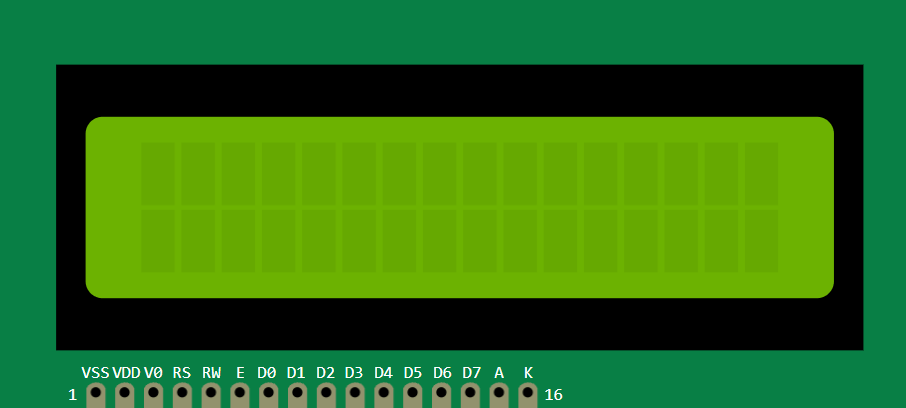
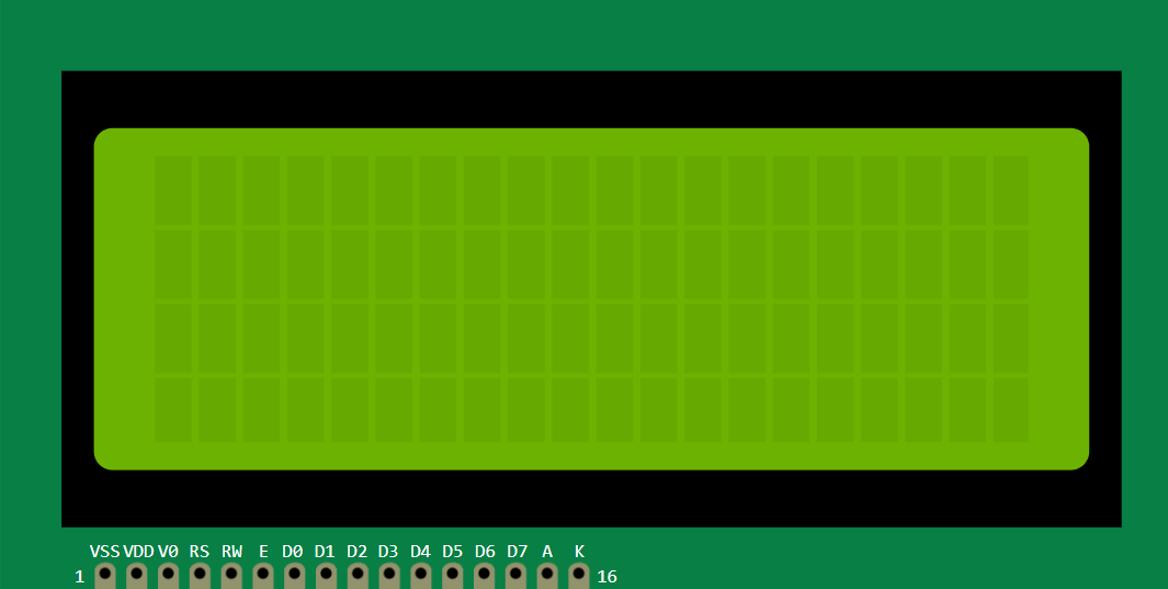
People often compare the ILI9341 with a common character LCD because both are used to show information on Arduino projects. The real difference is that they do not solve the same problem. A common LCD is best when you only need simple text, while the ILI9341 is for projects that need color, graphics, and a more polished interface.
| TFT display (ILI9341) | Common LCD |
|---|---|
| Shows color graphics, icons, and UI layouts | Shows text and basic symbols |
| Feels like a small screen | Feels like a simple status panel |
| Useful for dashboards and visual menus | Useful for readings, menus, and short messages |
| Needs more drawing logic in code | Usually easier for very simple projects |
In real use, this difference matters a lot. If your project only needs a temperature number or a short warning message, a common LCD is usually enough. But if you want charts, large labels, colored states, or a cleaner looking interface, the ILI9341 feels much more complete. That is why people pick it when the screen itself is part of the project experience, not just a place to print text.
Use a common LCD when you want simplicity. Use the ILI9341 when the display needs to look and behave like a real interface.
Features
Here are the main things to know about the ILI9341:
| Feature | What it means |
|---|---|
| Color TFT | Can draw full-color graphics and text. |
| 240x320 resolution | Gives enough detail for menus and small dashboards. |
| SPI interface | Uses a fast serial bus instead of many parallel lines. |
| Graphics friendly | Works well with Adafruit_GFX and Adafruit_ILI9341. |
| Good for UI | Useful for icons, labels, charts, and widgets. |
| Beginner friendly | Easy to test with a simple text and color example. |
The most important thing is that it can show both text and graphics, so your project can feel much closer to a real user interface.
How Does It Work?
The ILI9341 receives drawing commands over SPI. The Arduino tells the display what to draw, where to place it, and which color to use. The controller then updates the screen pixel by pixel.
Because it is a graphics display, the code is not limited to rows of characters. The sketch can draw boxes, lines, text, and shapes in whatever layout best fits the project idea.
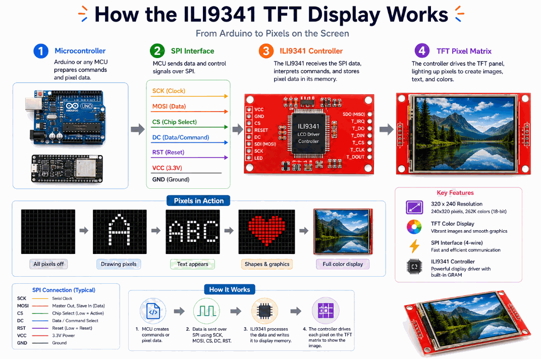
SPI Data Flow
The MOSI and SCK pins carry the data and clock signals, so the Arduino can send screen commands at a speed that feels fast enough for graphics instead of just text.
The CS and D/C pins tell the display when the Arduino is sending a command and when it is sending pixel data. That distinction matters because the controller needs to know whether it should change a setting, draw a shape, or push new color values into the screen memory.
In a typical setup, this small set of wires is enough to drive the whole panel. That is why the ILI9341 can look simple from the outside even though it is handling a lot of pixel work behind the scenes.
Frame Updates
The graphics library usually draws into an internal buffer first and then updates the screen. That gives the code a place to prepare the image before it becomes visible, which helps avoid flicker when the layout changes.
Once the frame is ready, the display updates in one cleaner pass instead of repainting one tiny piece at a time. On the user's side, that usually feels smoother and easier to read, especially when numbers or colored blocks change quickly.
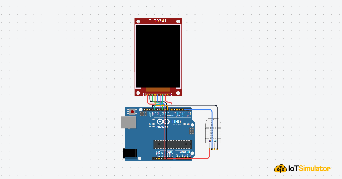
Arduino With ILI9341
The Arduino setup is straightforward once you separate the SPI lines from the control pins. The display uses the SPI bus for fast drawing, while the chip-select, data/command, reset, and backlight pins keep the panel behaving the way the sketch expects.
In a small demo, that usually means you can start with a title, then add shapes or color blocks once the panel is responding correctly. That makes the display easier to test one step at a time instead of trying to build the whole UI all at once.

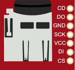
Pin Connection
The pin map is short once you group the display into power, SPI data, control, and backlight pins. For this article, the wiring keeps the common Arduino Uno SPI pins visible so the code and the circuit preview stay in sync.
Powers the display module.
Shares the same ground reference with the Arduino.
Selects the display on the SPI bus.
Tells the display whether the data is a command or pixel data.
Resets the display controller when needed.
Carries data from the Arduino to the display.
Carries the SPI clock signal.
Controls the backlight in this example setup.
Code
This example prints a title and a few colored lines on the screen. It is a simple first test that shows whether the display, SPI wiring, and graphics library are working correctly.
Once this works, you can expand it into a menu, a graph, a gauge, or a real dashboard for sensors and controls.
How The Code Works, Part By Part
Let's break the sketch into smaller pieces so the display workflow is easier to understand and easier to modify later.
Libraries
The sketch loads SPI and the Adafruit graphics libraries. Those libraries provide the communication layer and the drawing functions needed by the TFT panel.
Display Object
The display object stores the chip-select, data/command, and reset pins. That tells the library which pins the Arduino uses to talk to the panel.
Setup
In setup(), the code starts the display, turns on the backlight, clears the screen, and draws the first frame. This is where the screen gets its initial look.
Draw Shapes
The example draws a rectangle, a circle, and a line so you can see that the display can handle more than just text.
Repeat
This starter example does not need a repeating animation loop. In a real project, the loop would refresh sensor values, animation frames, or user interface changes when something on the screen needs to update.
Wrapping Up
The ILI9341 is easiest to use with an Arduino graphics library such as Adafruit_GFX plus an ILI9341 driver, because that library handles the screen commands, drawing functions, and coordinate setup for you.
Once you understand the SPI pins, the graphics libraries, and the frame-drawing idea, you can build touch-style menus, dashboards, and richer visual interfaces with confidence.
It is especially useful when the project needs to show more than one thing at once. A sensor value can sit beside a colored bar, a status icon can sit beside a label, and the display can make the whole project feel much more complete without forcing you into a complicated UI framework.
That is why the ILI9341 is one of the nicer display choices for learning. It gives you enough room to experiment with layout and color, but the wiring and code are still manageable once the SPI pins are set correctly.