This article is a guide about the LED. We will explain how it works, show its wiring, and walk through an Arduino example you can use in your own projects.
LEDs are one of the first output parts people learn because they make a project feel alive right away. You can use them for simple status lights, warnings, progress indicators, and many other small visual signals.
Description
LED stands for light-emitting diode. That means it is a diode that gives off light when current flows through it in the correct direction. Because it is a diode, polarity matters, so the LED must be connected the right way around.
In small Arduino projects, LEDs are often used as indicators for power, warnings, sensor states, or user feedback. They are also very common in learning examples because the result is easy to see and the code is short enough for beginners to follow.
Most hobby LEDs come in many colors and package styles, but the basic idea stays the same. Once you understand the polarity and current limits, you can use the same concept in almost any circuit that needs a simple light output.
Features
Here are the main things to know about an LED:
| Feature | What it means |
|---|---|
| Polarity sensitive | Must be connected in the correct direction |
| Forward voltage | Needs enough voltage before it lights up |
| Current limited | Needs a resistor in series for safe use |
| Fast response | Turns on and off instantly in code |
| Many colors | Available in red, green, blue, yellow, white, and more |
| Low power output | Perfect for indicators and small visual signals |
LEDs are simple, but they are not just tiny bulbs. They are electronic components with a clear direction of flow, so the wiring and resistor choice both matter when you want a stable and safe circuit.
How Does It Work?
An LED lights up when current flows from the anode to the cathode. The Arduino does not create light by itself; it simply provides a voltage difference that allows current to pass through the LED when the circuit is wired correctly.
That is why the same LED can behave very differently depending on how it is connected. If the polarity is reversed, the LED usually stays off. If the current is not limited, the LED can become too bright, draw too much current, and stop behaving safely.
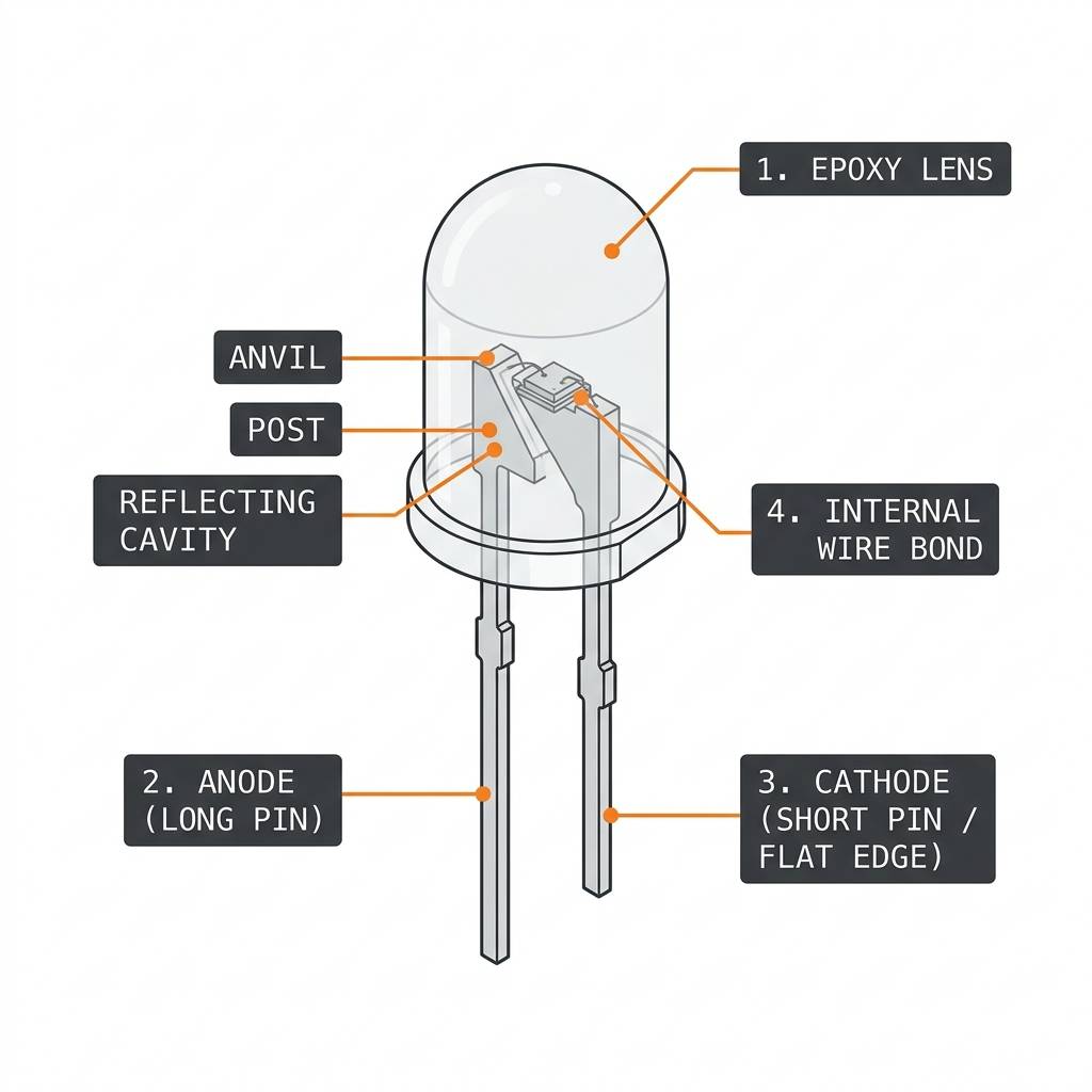
Polarity And Direction
The longer leg is usually the anode, which is the positive side. The shorter leg is usually the cathode, which is the negative side. Many LEDs also have a flat edge on the casing to help identify the cathode side.
When you are unsure, the safest habit is to check the physical marks on the package and verify the wiring before powering the circuit. A reversed LED usually will not light, but correct polarity gives you a clean and predictable result.
Forward Voltage
Every LED needs a certain forward voltage before it begins to light. That value depends on the color and construction of the LED, and it is one reason different colors can behave a little differently in the same circuit.
In practice, you do not need to memorize a perfect number for every LED. What matters is understanding that the LED needs enough voltage to turn on, but not so much current that it is stressed or damaged.
Current Limiting Resistor
A resistor in series with the LED helps control the current. That keeps the LED within a safer range and helps the brightness stay predictable instead of being driven too hard.
This is the most important wiring rule for beginners: always add a resistor when you connect a standard LED to an Arduino pin. The exact value depends on your supply voltage, LED color, and brightness target, but the idea is always the same: protect the LED by limiting current.
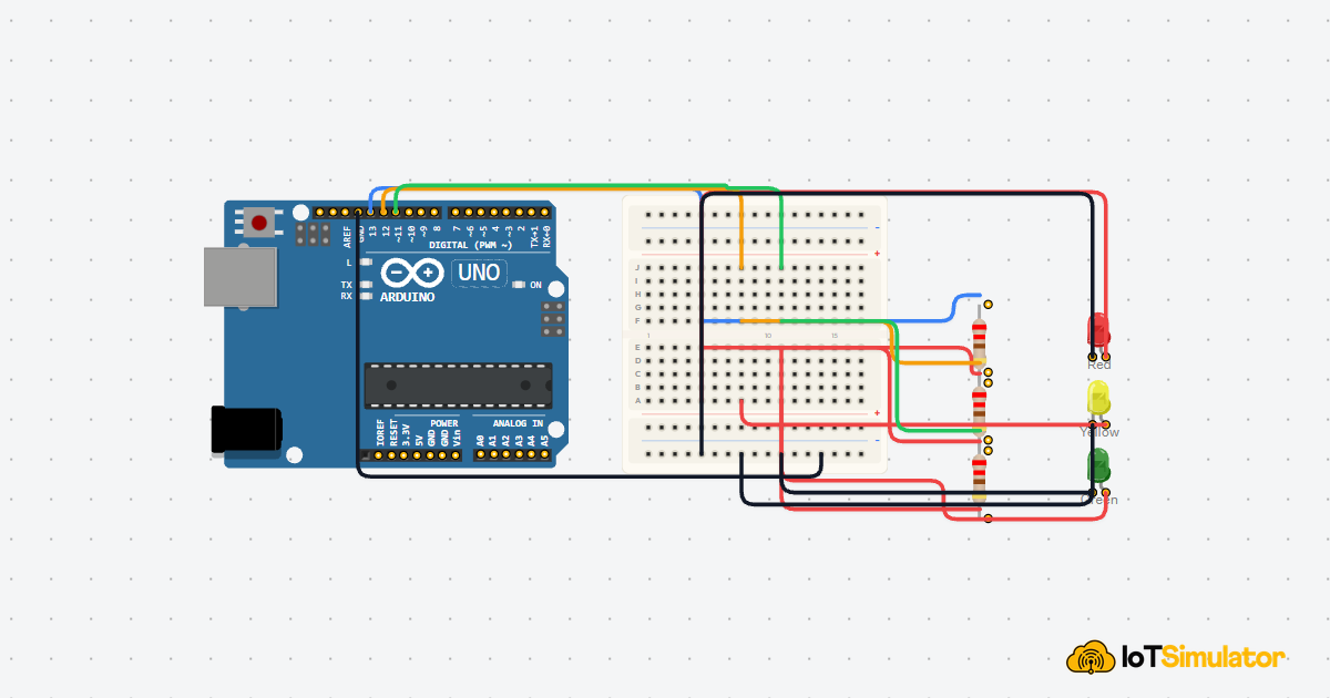
LED Wiring
The simplest Arduino wiring uses one digital pin, one resistor, and one LED. The pin drives the LED, the resistor limits the current, and the ground connection closes the circuit.
| LED Side | Arduino Uno |
|---|---|
Anode | Digital pin 13 through a resistor |
Cathode | GND |
For a beginner project, start with one LED on one output pin. That makes it easy to test the circuit, verify the resistor placement, and confirm that the Arduino code and hardware are working together.
Arduino With LED

This circuit shows the normal LED flow: the Arduino sends power through a resistor, the LED lights up, and the current returns to ground.
Code
This example uses the classic Blink pattern. The pin goes HIGH to turn the LED on, then LOW to turn it off again after a short delay.
You can use the same pattern for status lights, warning indicators, and any project where you want a quick visual response from the board.
How The Code Works, Part By Part
Let's break the sketch into small pieces so the behavior is easy to follow.
Pin Setup
First, the sketch stores the LED pin number in a variable and sets that pin as an output in setup(). That tells the Arduino this pin will drive a device instead of reading one.
Turn On
When the sketch writes HIGH to the pin, the pin provides voltage to the LED path. If the LED and resistor are wired correctly, the LED turns on.
Turn Off
When the sketch writes LOW, the voltage difference disappears and the LED goes off. That creates the visible blinking effect.
Repeat
The loop() function runs over and over again, so the on and off pattern keeps repeating without extra code. That is the whole idea behind the Blink example.
Wrapping Up
LEDs are one of the easiest ways to make an Arduino project visible. Once you understand polarity, forward voltage, and current limiting, the rest of the code becomes very simple.
That is why LEDs are so useful for beginner learning and for real projects alike. They turn a digital output into a clear visual signal that is easy to test, easy to debug, and easy to expand later.