This article is a guide about the MPU6050. We will explain how it works, show how to wire it to an Arduino, and walk through a simple example you can use in your own projects.
The MPU6050 is useful when a project needs to sense tilt, movement, rotation, or orientation changes. It gives the board a way to understand motion instead of just reading a button or a static sensor value.
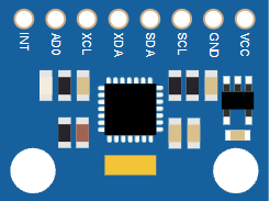
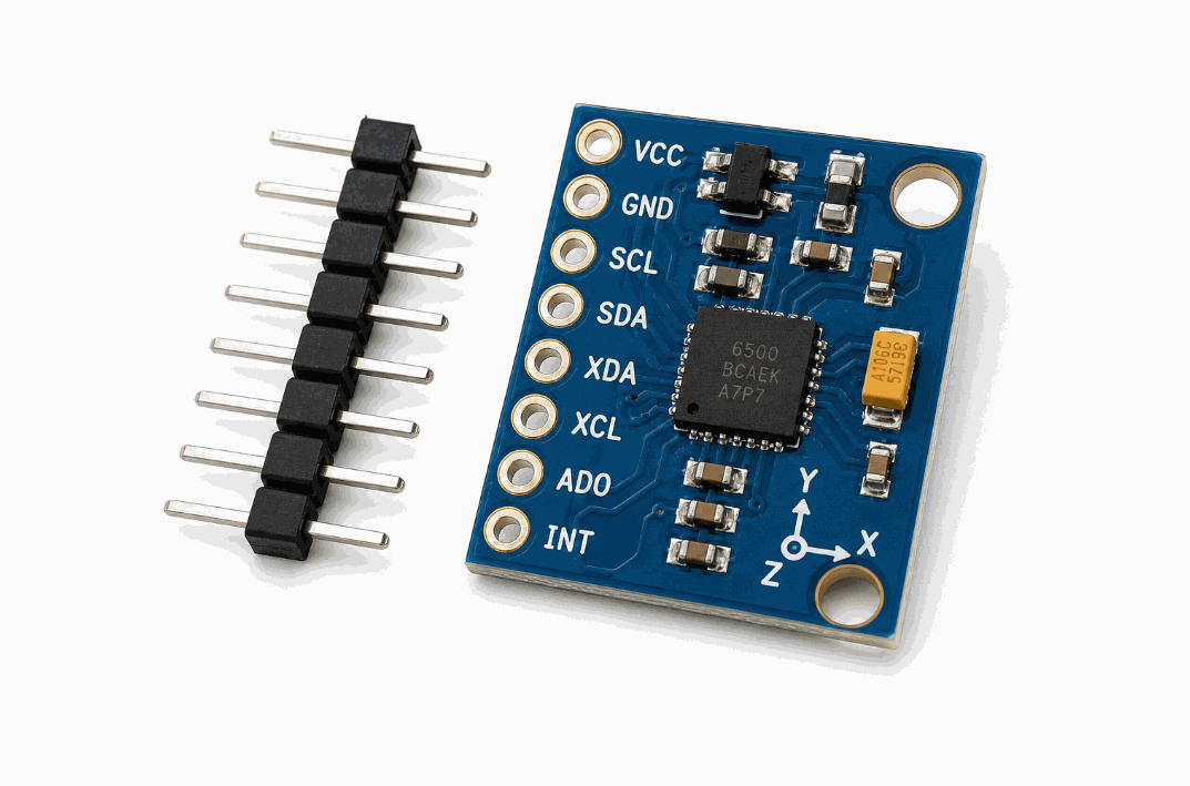
Before we jump into the details, it helps to look at the real module first so the chip layout, pin side, and board shape are easier to understand.
Description
The MPU6050 is a six-axis motion sensor. It combines a three-axis accelerometer, a three-axis gyroscope, and a temperature sensor into one small I2C module. That makes it a very useful part for projects that need to understand movement in space rather than just a simple on/off signal.
In beginner projects, it can help you detect tilt, shake, rotation, or orientation. In more advanced projects, it can support robotics, self-balancing behavior, gesture ideas, and motion visualization.
Some breakout boards look a little different, but the role is the same: the chip measures motion, and the Arduino reads those measurements over I2C.
Features
Here are the main things to know about the MPU6050:
| Feature | What it means |
|---|---|
| 6-axis sensing | Combines a 3-axis accelerometer and 3-axis gyroscope in one module. |
| I2C interface | Uses only SDA and SCL for communication. |
| Acceleration ranges | Common library ranges include ±2g, ±4g, ±8g, and ±16g. |
| Gyro ranges | Common library ranges include ±250, ±500, ±1000, and ±2000 degrees per second. |
| Temperature output | Provides an onboard temperature reading for extra context. |
| Optional address pin | AD0 changes the I2C address when needed. |
| Interrupt support | INT can be used for event-driven motion handling. |
| Beginner friendly | Good first IMU for tilt, shake, and rotation projects. |
The useful part is that the module gives the Arduino a lot of motion information while still using a small number of wires. That makes it much easier to add motion sensing without turning the wiring into a mess.
How Does It Work?
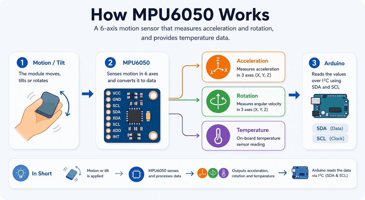
The accelerometer inside the module measures how gravity and movement affect the sensor on each axis. The gyroscope measures how fast the sensor is rotating. Together, those readings give the Arduino a picture of how the board is moving in space.
The sensor sends this data over I2C. The Arduino reads the values from SDA and SCL, then the sketch can print them, smooth them, or use them to control another part of the project.
The sensor also includes an onboard temperature reading, which is useful when you want to understand the module state a little better while testing. It is not a room thermostat, but it gives a real reading that can help you confirm the module is alive and responding.
Technical Notes
The MPU6050 is commonly used as an IMU, which is short for inertial measurement unit. In practical terms, that means the chip is built to watch motion rather than distance or light. The accelerometer responds to linear movement and gravity, while the gyroscope responds to rotational movement.
Most Arduino libraries let you choose motion ranges for the accelerometer and gyroscope. A smaller range can feel more sensitive when you only want subtle tilt changes, while a larger range is better when the sensor may move more aggressively, such as on a robot or a handheld project. If you choose a range that is too small, the readings can clip when motion gets stronger. If you choose a range that is too large, the values can feel less precise for tiny movements.
That range choice is one of the details that makes the sensor feel more technical than a simple input part. Once you understand it, though, the module becomes much easier to tune for the job you want.
Main Uses
The MPU6050 is most useful when the project needs to react to motion instead of a simple button press. These three examples show the most common ways people use it in beginner and intermediate Arduino builds.
Detecting Tilt
Tilt detection is the easiest place to start. The accelerometer can tell when the board leans forward, backward, left, or right, which makes it useful for simple angle warnings, balance checks, and menus that respond to direction.
Detecting Rotation
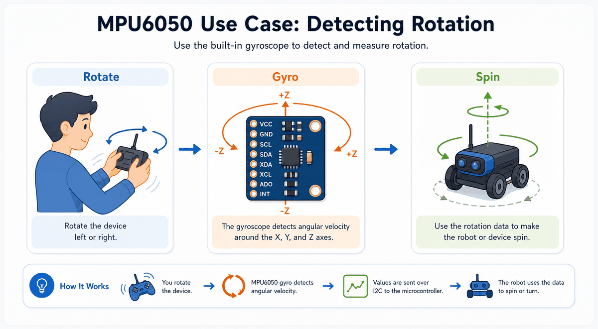
Rotation uses the gyroscope side of the chip. This is the part you want when the project needs to know how fast something is turning, such as a handheld controller, a robot body, or a moving display mount.
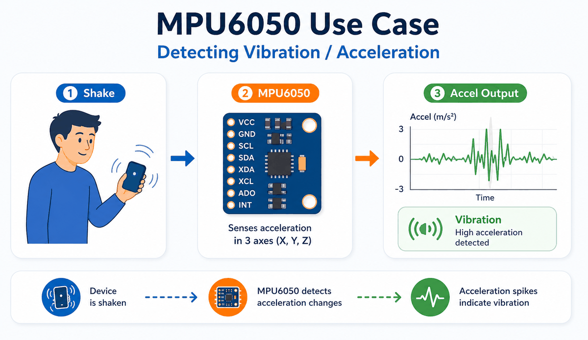
Detecting Vibration And Acceleration

Vibration and acceleration detection are useful when the board is shaken, bumped, or moved quickly. In practice, this can trigger alarms, motion logs, or simple event counters, and it gives you a clean way to turn sudden movement into something the sketch can react to.
MPU6050 Pinout
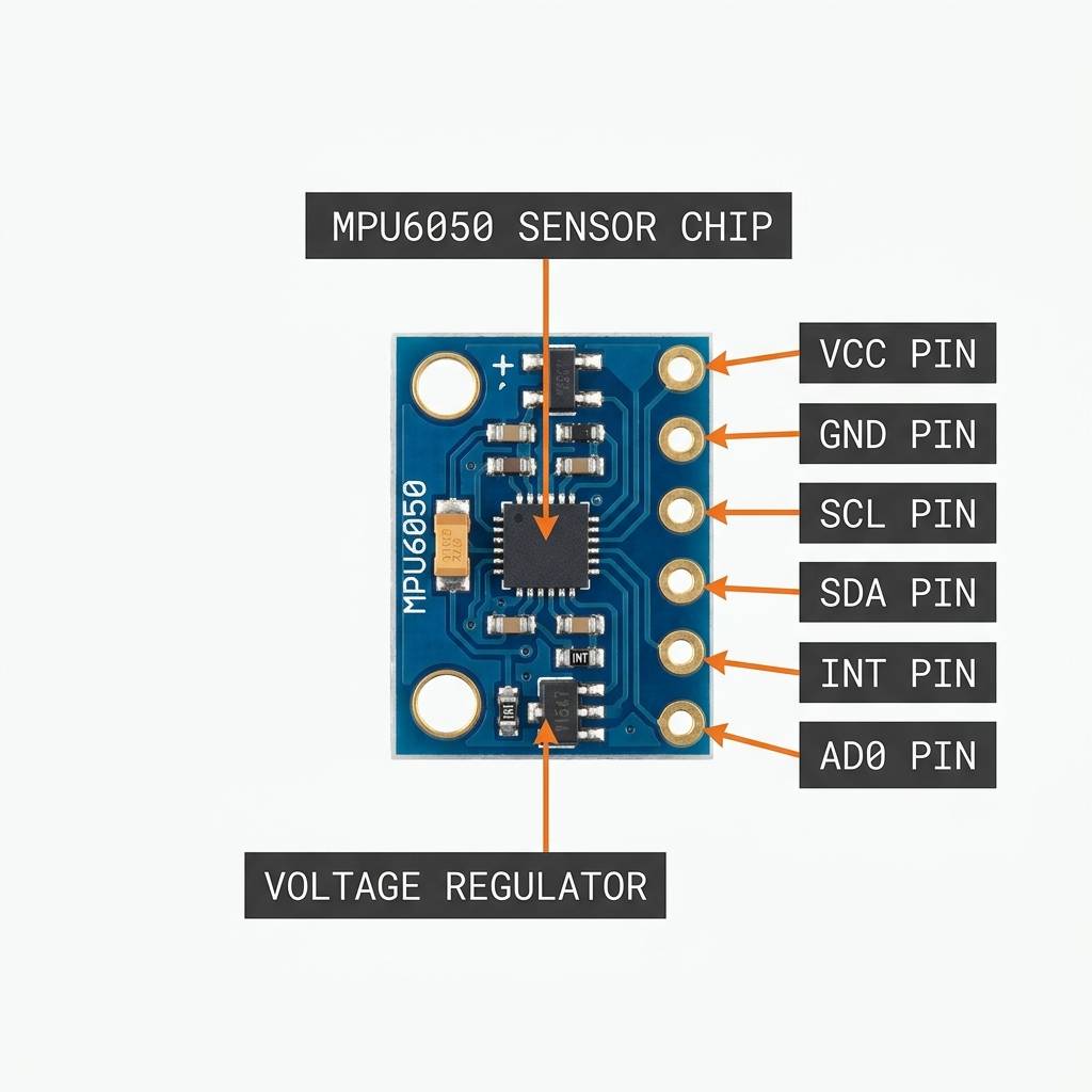
The MPU6050 breakout board usually exposes a small set of pins around the edge of the module. The exact board layout can vary a little between versions, but the functional pins stay the same, which is what matters for wiring and code.
| Pin | Meaning |
|---|---|
VCC | Powers the module. |
GND | Ground reference for the sensor. |
SDA | I2C data line. |
SCL | I2C clock line. |
AD0 | Changes the I2C address when needed. |
INT | Interrupt output for motion events. |
XDA | Auxiliary data pin, usually unused in beginner builds. |
XCL | Auxiliary clock pin, usually unused in beginner builds. |
For a basic project, the most important pins are still VCC, GND, SDA, and SCL. The extra pins are useful when you want more control, but they are not required for the simple motion sketch later in the article.
Arduino With MPU6050

This circuit preview shows the MPU6050 connected to an Arduino Uno so you can see the I2C layout before reading the sketch. The sensor only needs a few wires for the basic setup, which is why it stays popular in small motion projects.
Pin Connection
The pin connection map below shows the common Arduino Uno wiring for the MPU6050. If the I2C lines are swapped or the power pins are wrong, the sensor often fails to initialize cleanly.
Powers the breakout board and the sensor chip.
Shares the same electrical reference as the Arduino.
Carries I2C data between the Arduino and the sensor.
Carries the I2C clock that keeps communication in step.
Optional address-select pin used when you need a second I2C address.
Optional interrupt line for event-driven motion handling.
Once the wiring matches the I2C pins, the sensor usually becomes straightforward to use. If it still refuses to respond, the first things worth checking are the SDA and SCL lines, because those decide whether the Arduino can actually talk to the chip.
Arduino Code
This example uses the Adafruit MPU6050 library to read accelerometer values and print them to Serial Monitor. It is a strong starting point for motion-visualization or tilt-detection projects.
About Adafruit MPU6050 Library
The Adafruit_MPU6050 library handles the setup and register work so the sketch can focus on reading motion values. It gives you a clean way to start the sensor, choose ranges, and read acceleration, rotation, and temperature as structured events.
That matters because the MPU6050 is a real motion sensor, not just a basic digital input. The library keeps the code readable while still exposing enough control to tune the range and data format for the project you are building.
If you are only printing values for testing, the default setup is often enough. If you want smoother tilt detection or a stronger motion response, the library also lets you adjust the ranges so the readings fit the job better.
The sketch prints the acceleration values every half second. In a real project, you can use those readings to detect tilt, movement, or orientation changes instead of just printing them.
How The Code Works, Part By Part
Let's break the sketch into smaller pieces so the flow is easier to understand and easier to modify later.
Setup
The setup block starts the serial monitor, prepares the library, and checks whether the sensor is connected. If the sensor is missing, the sketch stops so you know something is wrong with the wiring.
Read Motion Data
This part asks the sensor for acceleration, gyroscope, and temperature events. Those readings are the raw motion values your sketch can use.
Output The Values
Here the sketch prints the acceleration data so you can watch the values change while the sensor moves. That makes it easier to understand the axis readings before building a bigger project.
Wrapping Up
The MPU6050 is a powerful motion sensor when you want the Arduino to understand tilt, rotation, and movement. It is small, flexible, and useful in a wide range of beginner and advanced projects.
Once you understand the I2C wiring, the axis values, and the range settings, the sensor becomes much easier to use in real projects. That is the part that matters most in practice: a well-wired MPU6050 can tell you not just that something moved, but how it moved and how fast it moved.
From here, a good next step is to turn the readings into a simple tilt warning, a motion-controlled menu, or a balance demo that reacts to the board being rotated. That gives the sensor a clear job and makes the motion data easier to picture while you are testing.