This article is a guide about the Slide Switch. It shows how a maintained switch gives the Arduino a stable choice instead of a momentary press.
Slide switches are useful when a project needs a clear physical on/off or left/right selection input. That makes them a good fit for power choices, mode selectors, and simple manual overrides.
Description
The slide switch is a maintained switch, which means it stays in the chosen position until you move it again. That makes it different from a pushbutton, which only stays active while it is pressed.
Because it is a maintained switch, it is often used for power selection, mode switching, and simple control logic. It gives the Arduino a clear digital state instead of a changing analog value.
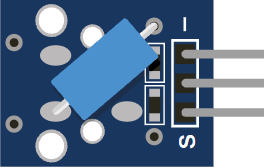
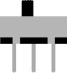
In the simulator, the slide switch is a three-pin SPDT switch, so the middle pin acts as the common contact and connects to either side depending on the slider position.
Features
Here are the main things to know about the Slide Switch:
| Feature | What it means |
|---|---|
| Maintained position | Stays where you place it until you slide it again. |
| SPDT layout | Uses one common pin and two selectable terminals. |
| Digital input | Best for on/off or left/right style logic. |
| Simple wiring | Easy to connect to a microcontroller pin with a pull-up. |
| Beginner friendly | Good for learning how switches map to code states. |
The important part is that the switch gives you a stable state, so the code does not need to guess whether the user is still interacting with it. That is what makes it good for power switches and mode selectors.
How Does It Work?
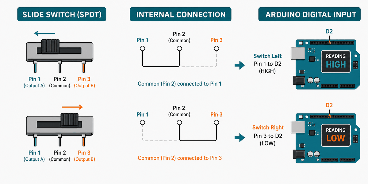
An SPDT slide switch has one common terminal in the middle and two outer terminals on the sides. When you slide the handle, the common pin connects to one outer pin or the other.
That means the Arduino can read the switch as a clear logic state. If you wire the common pin to an input and use a pull-up resistor, the pin reads one way in one position and the opposite way in the other position.
This makes the slide switch very useful for mode selection. A single physical movement can tell the sketch to choose between two behaviors, two screens, or two output states.
SPDT Behavior
SPDT stands for Single Pole Double Throw. In practice, that means one shared connection can be thrown to either the left side or the right side, depending on where the slider is placed.
State Logic
Because the switch holds its position, the Arduino can read it as a stable digital input. That is why it works well for on/off settings and mode selectors.
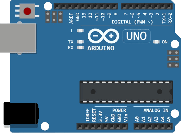
Arduino With Slide Switch
This circuit preview shows the slide switch connected to Arduino Uno. It is a clean example of a maintained digital input because the switch stays in place and gives the Arduino a stable state.

Pin Connection
The pin map below matches the circuit preview. The middle pin acts as the common contact, and one outer pin goes to ground so the Arduino can read a stable on/off state.
Common contact that the Arduino reads.
One selectable side of the switch.
The other selectable side can be used for a second state if needed.
With this wiring, the switch does not need any special library. The Arduino only needs a digital read, which keeps the code simple.
Code
This example reads the switch and prints which side is selected. It is a simple way to confirm that the wiring and pull-up logic are working.
Once that works, you can use the switch to select between two modes, start and stop a feature, or change which output should run. That is the main strength of a slide switch: it gives the project a clear physical choice.
How The Code Works, Part By Part
Let's break the sketch into smaller pieces so the flow is easier to understand and easier to modify later.
Setup
The setup block starts Serial Monitor and enables the internal pull-up resistor. That makes the input stable without needing an external resistor in many simple builds.
Read State
The sketch reads the switch pin as a digital value. That gives you a clean HIGH or LOW state to work with.
Check Position
The code decides which message to print based on the current switch state. This is the point where the physical switch becomes a software choice.
Repeat
The short delay keeps the output readable while the sketch continues checking the switch position.
Wrapping Up
The slide switch is a simple but useful input part when you want a stable physical selector. It is one of the easiest ways to give an Arduino a lasting choice instead of a momentary press.
Once you understand the common pin, the two outer terminals, and the pull-up logic, you can use it confidently in mode selection and digital control projects. The result is usually very easy to debug because the switch position stays visible to the user.