This article is a beginner guide to the Biaxial Stepper module. We will start with what the part is, then look at its pinout, show how to connect it to an Arduino, and finally walk through a simple example sketch.
What makes this part worth studying is not just that it has two shafts, but that both shafts are visible and easy to compare. That gives beginners a clear way to learn stepper motion without a lot of extra hardware.
By the end of the article, you should understand how the two shafts are arranged, what the pin names mean, and why this module is a neat example of two-part motion in one small package.
Description
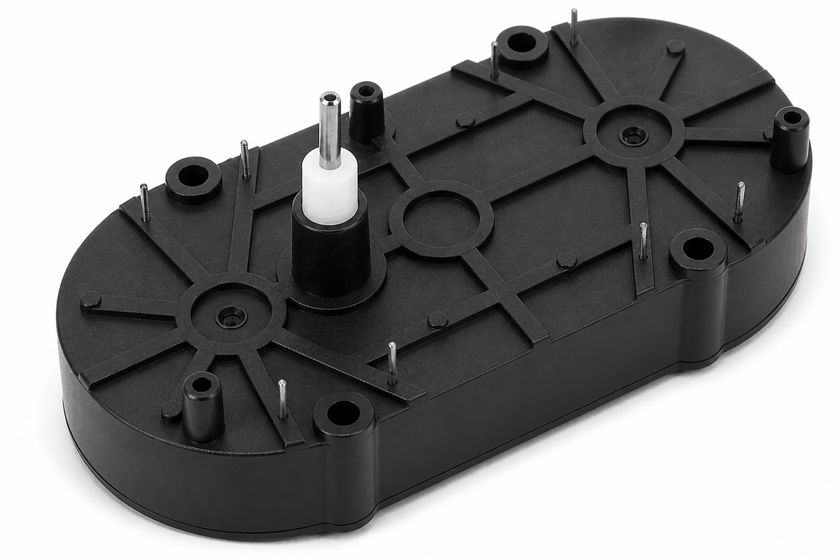
The Biaxial Stepper looks like one module, but it behaves like two stepper motors in one body. It has an outer shaft and an inner shaft, and each shaft can move separately.
That is the useful part: you can compare the two shafts side by side and immediately see what your code is doing. For a beginner, that is much easier to understand than a motor hidden inside a larger machine.
The module uses eight coil pins in total. Four pins belong to the outer shaft and four pins belong to the inner shaft, so each shaft gets its own pair of coil connections. That split is what makes the module feel simple once you learn the pin names.
Features
Here are the main things to know about the Biaxial Stepper:
| Feature | What it means |
|---|---|
| Two shafts | One module gives you an outer shaft and an inner shaft. |
| Eight coil pins | Each shaft has its own coil connections. |
| Separate movement | Both shafts can move on their own. |
| Good for learning | Helps you practice moving two parts from one Arduino. |
| Small layout | Keeps the two shafts in one compact module. |
| Simple step control | Works well with Arduino step-by-step motion code. |
The main thing to remember is simple: the two shafts are separate, so your code can move one shaft, the other shaft, or both together. That is the part that makes the module fun to use instead of just another motor block.
Common Uses
This module is useful when you want two rotating parts in one build. It keeps the project compact while still letting each shaft move on its own.
Clock hands and dials: This is probably the clearest use case. One shaft becomes the outer hand, the other becomes the inner hand, and the whole idea makes instant sense when you see it move.
Layered motion demos: You can move one shaft by itself, or make both shafts move in different directions. That makes the module great for showing motion in a way that feels obvious instead of abstract.
Learning dual-motor control: If you are learning stepper control, this is one of the friendliest ways to practice because the result is easy to see and easy to debug.
How Does It Work?
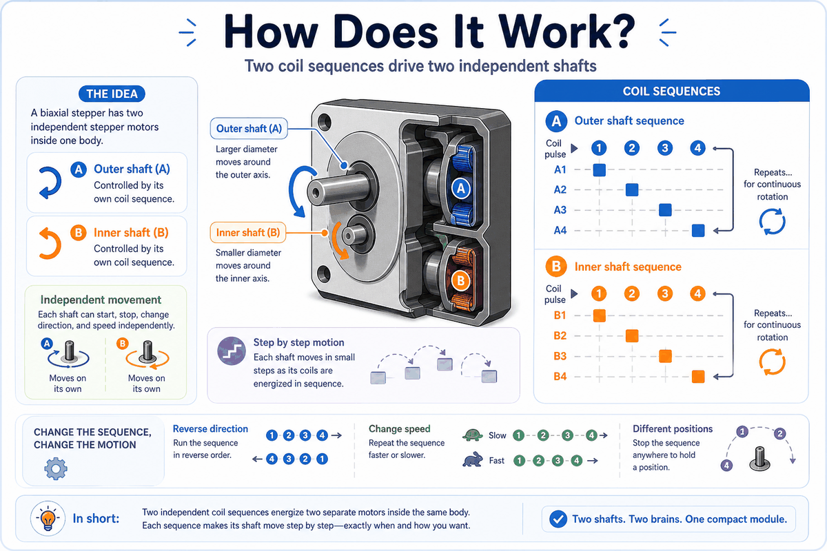
A stepper motor moves in small steps instead of spinning freely. The Arduino turns the coils on and off in a set order, and each small change pushes the shaft a little bit forward. That is why a stepper feels more precise than a regular spinning motor.
The Biaxial Stepper uses that same idea twice. The outer shaft follows one coil order, and the inner shaft follows another. That means the two shafts can move in different ways even though they share the same module. This is the part that makes the module more interesting than a basic single-shaft motor.
If the coil order changes, the direction changes too. If the steps happen faster, the shaft turns faster. If the steps slow down, the movement becomes slower and easier to watch. So the sketch is really controlling both direction and speed through the order of the coil signals.
Because the motor moves in steps, it can also stop at a chosen position and stay there instead of drifting freely. That is one of the main reasons stepper motors are useful in pointer displays and simple positioning projects.
The order of the coil signals matters too. If the sketch sends the signals in the wrong order, the shaft may move the wrong way or feel jerky. When the order is correct, the movement is steady and easy to control. For this module, that makes the code feel very direct: the sequence you write is the movement you get.
The two shafts do not have to move the same number of steps. One shaft can turn a full circle while the other only moves a small amount, which makes it easy to create simple layered motion without a lot of code. That is a very practical detail, because it lets you build simple animations without needing a big program.
Pinout
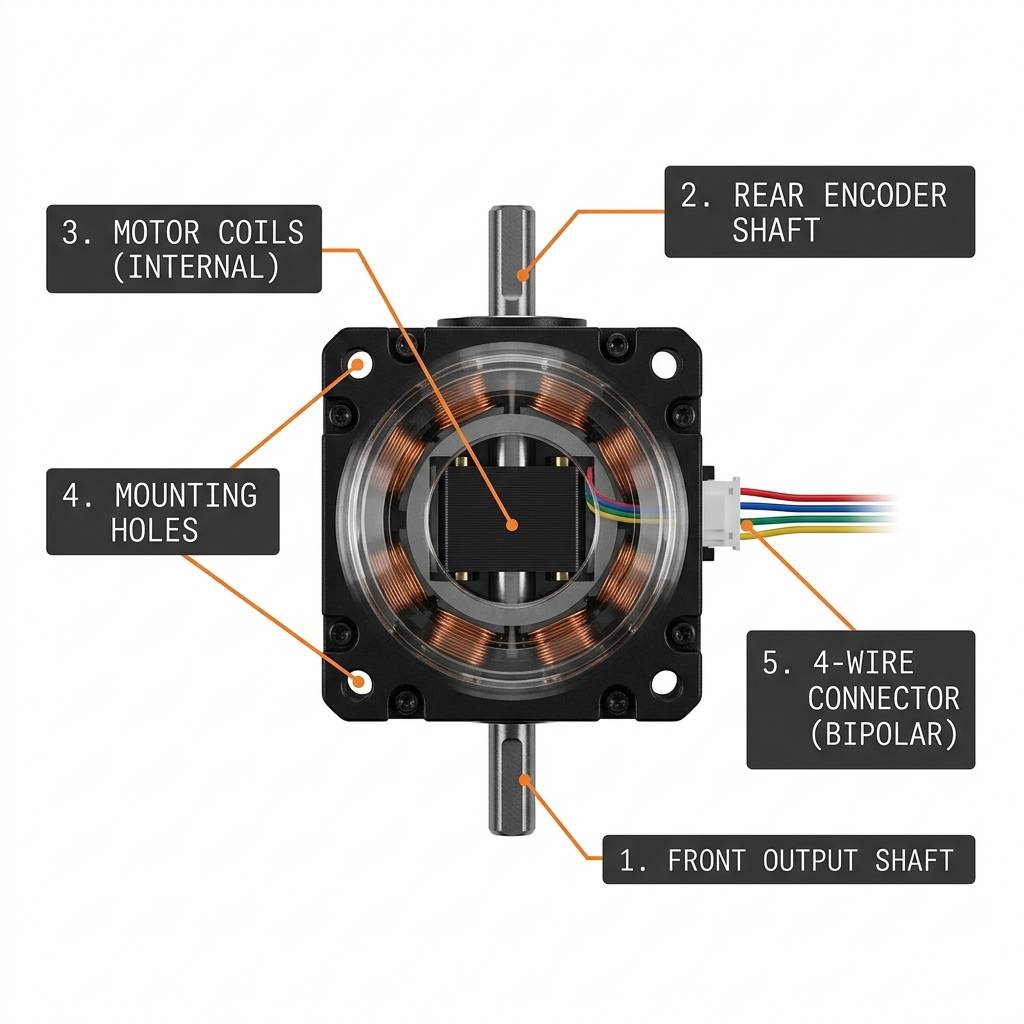
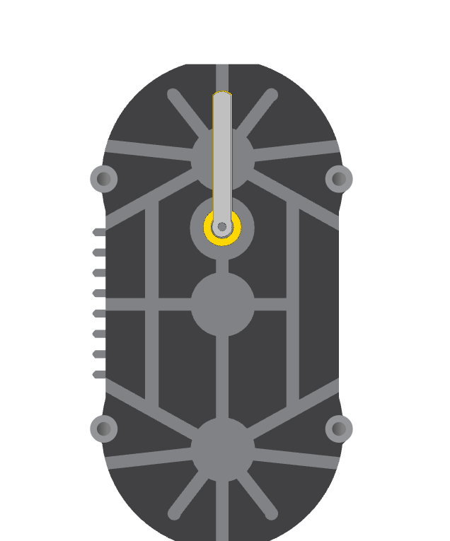
The anatomy view helps you match the shaft areas to their pin names. Even though the module looks like one part, the pinout is split into two groups, one for each shaft. Once you see that split, the wiring stops feeling confusing and starts feeling logical.
| Pin | Shaft | Meaning |
|---|---|---|
A1- | Outer shaft | First outer shaft connection. |
A1+ | Outer shaft | First outer shaft pair. |
B1+ | Outer shaft | Second outer shaft pair. |
B1- | Outer shaft | Second outer shaft connection. |
A2- | Inner shaft | First inner shaft connection. |
A2+ | Inner shaft | First inner shaft pair. |
B2+ | Inner shaft | Second inner shaft pair. |
B2- | Inner shaft | Second inner shaft connection. |
Coil Logic
Stepper coils are not like a simple LED that only turns on or off. The sketch steps through a pattern, and that pattern keeps the shaft moving in small, controlled steps. That pattern is the real trick behind the module.
Two Shafts, Two Patterns
Because the module has an inner and an outer shaft, the Arduino can move one shaft while the other stays still, or make both move together. That is why it works well for clock-style demos and other two-part motion projects. The best part is that the result is easy to understand just by watching it move.
The pinout map shows which pins belong to which shaft. Keep each pair together so the motion stays smooth and the sketch behaves the way you expect. If the pair is wrong, the motion usually feels wrong too, so this is one of the few places where careful wiring really matters.
The pin names split into two groups: A1-, A1+, B1+, B1- for the outer shaft, and A2-, A2+, B2+, B2- for the inner shaft.
Pin Groups
When wiring the module, keep each coil pair together. If a shaft turns the wrong way, swapping one pair is usually enough to fix it.
Arduino With Biaxial Stepper
The preview below shows a simple Arduino setup so you can see the biaxial stepper in context before looking at the code. The two shafts are connected to different pins, so you can understand how one sketch can move both parts separately. This is a good place to pause and look at the whole picture before jumping into the sketch.

For simulation, you can connect the motor directly to Arduino digital pins. For real hardware, a stepper driver is usually the safer choice because the motor needs more current than a board pin should provide. If you try it without a driver, the Arduino pins can get stressed quickly, and in practice the motor may just twitch, jitter, or stop before making a full turn. That is usually the first sign that the wiring needs a proper driver stage.
The Arduino Stepper library example uses the same basic idea: the coil order matters, the pin groups must stay in order, and the motor works best when the wiring matches the code. That is why the simulator wiring can stay simple, while a real build still needs a proper driver. The lesson here is simple: the code sequence and the wiring have to agree.
A driver helps protect the Arduino and gives the motor the power it needs. In simple terms, the Arduino sends the control signals and the driver handles the motor current. This is a good reminder that stepper motors are not just about movement; they are also about giving the motor enough power to behave cleanly.
In a learning setup, the direct connection is still useful because it shows how each coil line changes the motion. That makes the Biaxial Stepper easier to understand before you move on to a real hardware build. If you are teaching someone stepper basics, this is the kind of example that makes the idea click faster.
Code
This example uses two Stepper objects so you can control the outer and inner shafts separately. It is a simple starting point that shows the idea without adding extra complexity. What makes it useful is that it gives you a direct, readable map from code to motion.
With this sketch, the outer shaft turns one way while the inner shaft turns the opposite way. That makes it easy to see that the module really contains two separate moving parts. If you later switch to a driver-based build, the same step order still applies, so this is not throwaway example code.
How The Code Works, Part By Part
Let's break the sketch into smaller pieces so the flow is easier to understand and easier to modify later.
Library And Step Count
The sketch starts by loading the Stepper library and setting how many steps make one full turn. That gives both shafts the same reference point. Without that number, the code would not know what a full rotation means.
Create The Two Motors
Next, the sketch creates one Stepper object for the outer shaft and one for the inner shaft. Each object gets its own four coil pins, so the two parts can move separately. This is the part where the code starts matching the hardware very closely.
Set Speed
The setup block sets a different speed for each shaft. That makes it easy to see that the outer and inner parts do not have to move the same way. In practice, this is one of the simplest ways to make the two shafts feel distinct.
Move The Shafts
The loop rotates the outer shaft in one direction and the inner shaft in the opposite direction. This clearly shows that each shaft can move on its own. It is a very small sketch, but it demonstrates the whole idea of the module in a way that is hard to miss.
Repeat
The delay gives the movement a small pause before the pattern repeats. That pause makes the motion easier to follow in the simulator. It also keeps the motion from feeling too fast for a beginner to read.
Wrapping Up
The Biaxial Stepper is a good way to learn how two stepper motors can live inside one module and still be controlled separately. That combination of compact size and clear motion is the reason the part is worth studying.
Once you understand the pin groups, the two shaft layout, and the idea of repeated stepping, you can use this part confidently in small motion projects. If you only remember one thing from the article, remember this: the shaft that moves is the shaft that your code is stepping.