This article is a guide about the DIP Switch 8. We will explain what the switch bank is, how it works, how to wire it, and how to read the switch states from Arduino code. DIP switches are useful when a project needs several stable on/off settings in a compact format. They are especially handy when you want a physical setting that stays put instead of a button you must keep pressing.
Description
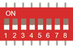
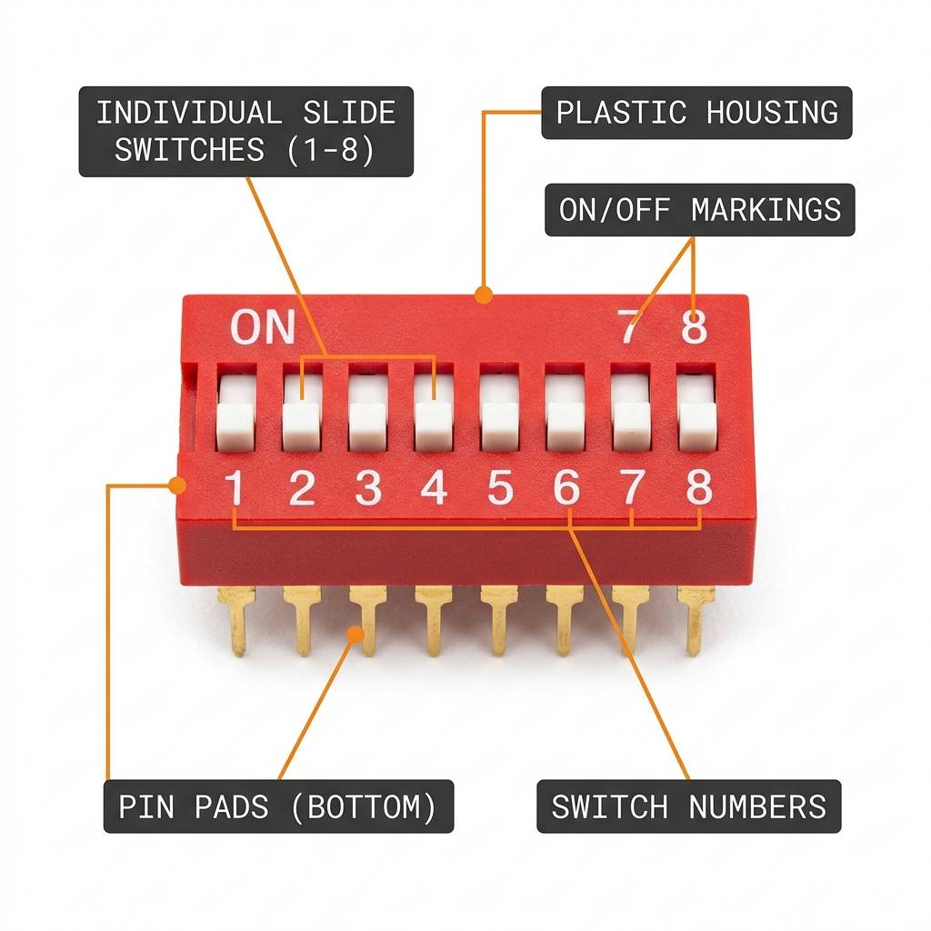
The DIP Switch 8 is a bank of eight tiny switches in one package. Each switch can be turned on or off independently, which makes the part useful for configuration settings, address selection, feature toggles, and binary input experiments.
Unlike a joystick or potentiometer, a DIP switch does not give a changing analog value. It gives you a set of clear digital states that stay where you leave them until you move the switch again. That is why it feels more like a tiny control panel than a sensor.
The wider DIP-switch family also includes other styles such as slide and rotary versions, but this 8-position bank is the familiar version for simple on/off settings. It is easy to understand, easy to test, and easy to use when a project needs a fixed hardware choice.
Features
Here are the main things to know about the DIP Switch 8:
| Feature | What it means |
|---|---|
| Eight inputs | Lets you control eight separate on/off states. |
| Binary style | Useful for setting values in bits and small codes. |
| Stable position | Stays in place until you move a switch again. |
| Simple wiring | Easy to connect with pull-up logic and digital inputs. |
| Configuration friendly | Good for board addresses, mode selection, and options. |
| Maintained input | Perfect for settings that should not change by accident. |
The important part is that each switch acts like a small maintained input, so the Arduino can read a whole group of settings all at once. In real use, that is what makes it better for setup choices than for fast user interaction.
How Does It Work?
Each tiny switch inside the DIP package connects or disconnects a circuit path. When a switch is on, the Arduino sees one logic state. When it is off, the Arduino sees the other state. That simple contact change is the whole trick behind the module.
Because the switches are independent, the sketch can read all eight positions and combine them into a binary number or a set of separate options. In practice, that means one small switch bank can replace a long string of hard-coded choices in your sketch.
This is why DIP switches are often used for configuration. They let a human choose a value before the board starts its main task, which is much more convenient than editing code every time you want to test a new mode.
Binary Value
Each switch can represent one bit. Eight switches can therefore represent values from 0 to 255, which is useful for addresses or configuration codes. That range is one reason the part shows up so often in board setup and binary input examples.
Stable Input
Because the switch stays in the chosen position, the Arduino can read it repeatedly without the state changing unless the user touches the hardware again. That is different from a pushbutton, which only stays active while you press it.
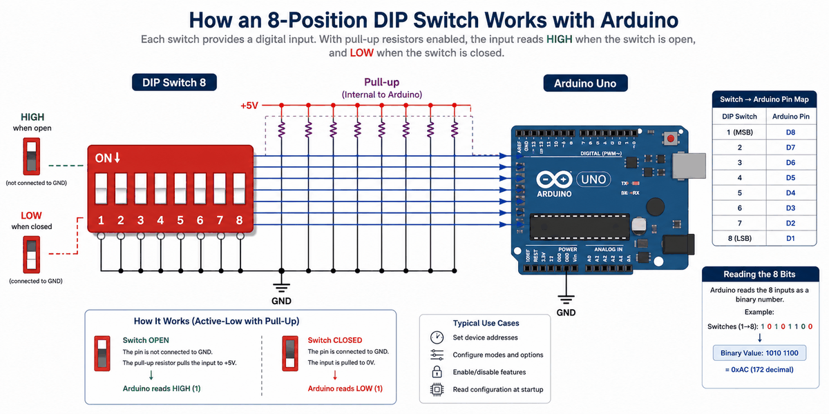
Active Low Wiring
A lot of beginner sketches read DIP switches with pull-up resistors. In that setup, an open switch reads HIGH and a closed switch pulls the pin LOW. This is a clean wiring pattern because the input never floats.
Pinout
The connection map tells you which pins matter most when wiring the module to an Arduino. Match the shared side and the read pins carefully so the circuit behaves the way the sketch expects.
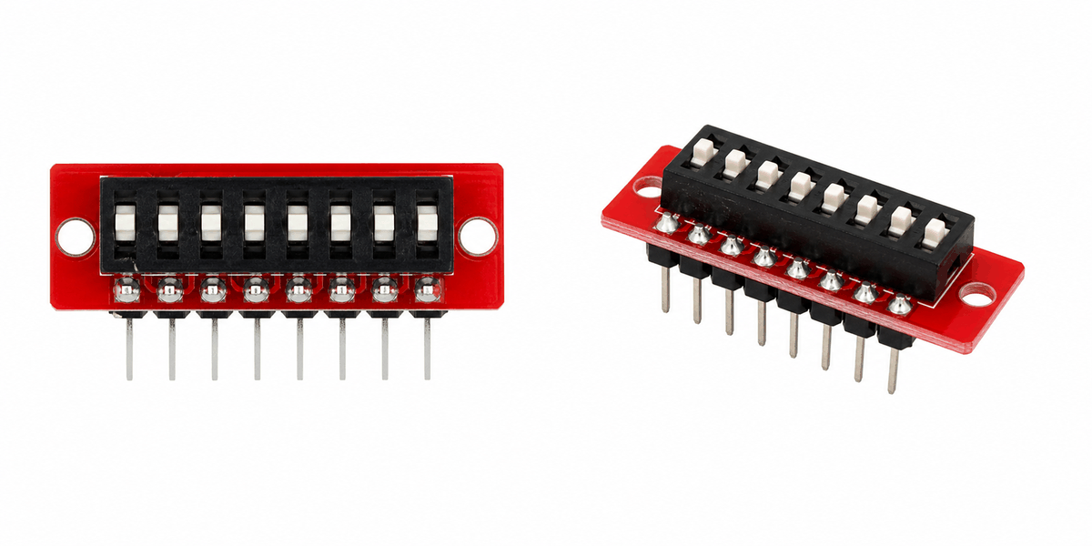
In this simulator, the DIP switch exposes sixteen pins: eight on one side and eight on the other. The switches are arranged as paired contacts, so each row position can be read as an independent on/off input. That is why the pinout feels simple once you understand that each switch is just a bridge between two pads.
Pin Role
In a basic input setup, one side of each switch connects to ground or power, and the other side connects to the Arduino input. Using a pull-up or pull-down arrangement keeps the reading stable. For this article's example, pull-up wiring is the easier choice because the Arduino can handle the default HIGH state on its own.
| Pin Group | Role | Connection | Notes |
|---|---|---|---|
1a-8a | Common side | GND | These pins share the ground reference for the active-low setup. |
1b-8b | Signal side | D2 to D9 | These pins go to the Arduino inputs so each switch can be read as a bit. |
Arduino With DIP Switch 8
The Arduino setup is simple: the switch bank feeds eight digital inputs, and the Arduino reads them as a fixed binary pattern. In this example, the switch positions are wired to pins D2 through D9, which matches the sketch below.
A common use case for this setup is a hardware configuration panel. You can use the switch bank to pick a board address, enable or disable a feature, or choose which mode the sketch should start in without opening the code editor.

Pin Connection
The pin connection is simple once you split the switch bank into a common side and a signal side. The table below shows how each row maps into the Arduino input pins used by the sketch.
The common side of the switch bank shares ground so the pull-up logic stays stable.
Reads bit 1 from the switch bank.
Reads bit 2 from the switch bank.
Reads bit 3 from the switch bank.
Reads bit 4 from the switch bank.
Reads bit 5 from the switch bank.
Reads bit 6 from the switch bank.
Reads bit 7 from the switch bank.
Reads bit 8 from the switch bank.
With INPUT_PULLUP enabled, the Arduino reads HIGH when a switch is open and LOW when it is closed. That active-low pattern keeps the inputs stable and makes the switch bank easier to debug in a simple Arduino sketch.
With INPUT_PULLUP enabled, an open switch reads HIGH and a closed switch reads LOW. That active-low pattern keeps the inputs stable and makes the switch bank easier to debug in a simple Arduino sketch.
Code
This example reads eight switch states and prints both the bit pattern and the final value to Serial Monitor so you can see the configuration settings change. It is a helpful first sketch because it shows how a physical switch position becomes a number in code.
Once that works, you can use the switch bank to set addresses, choose modes, or enable and disable features in your project. That is the main reason people keep using DIP switches even though the part looks very simple.
How The Code Works, Part By Part
Let's break the sketch into smaller pieces so the flow is easier to understand and easier to modify later.
Pin Array
The code begins by listing the eight Arduino pins connected to the switch bank. That makes the rest of the sketch easier to read and change later. When the pin list is clear, the binary logic becomes much easier to follow.
Input Mode
The setup block turns on the internal pull-up resistors. That keeps the input stable and avoids floating readings in a simple wiring setup. This is one of those small details that saves beginners a lot of confusion.
Read Switches
The loop checks every switch one by one. If a switch is active, the code adds that bit to the output value. In other words, the sketch is turning a row of tiny settings into one binary number.
Print Value
Printing the final value lets you see the combined switch state in one number, which is very helpful for addresses or option codes. It also gives you a quick way to confirm that the switch order matches your wiring plan.
Repeat
The delay gives the serial output a little breathing room while the sketch keeps checking the switch bank.
Wrapping Up
The DIP Switch 8 is a simple but powerful input part when you want a fixed set of binary options.
Once you understand the pull-up logic, the bit pattern, and the switch positions, you can use it confidently in configuration and control projects. It is one of the clearest parts for learning how hardware settings become code values.
If the output looks backwards, the first thing to check is the bit order and which switch maps to which Arduino pin. After that, you can reuse the same pattern for mode selection, startup options, and any project that needs a small hardware setting panel.