This article introduces the Heart Monitor module and shows how to wire it, read its output, and build a simple Arduino example around it. We will focus on the signal the sensor gives back, how to interpret it, and what to expect when you use it in a project.
It is a useful part for beginner pulse and fitness demos because it turns a real heartbeat into a changing signal the Arduino can work with.
Description
The Heart Monitor module is a pulse-sensor style part used to detect small changes in blood flow. In practice, a fingertip or earlobe is placed on the sensing area, and the module turns the changing light absorption into an electrical signal that Arduino can read.
That means the sensor is not measuring the heart directly. Instead, it is watching the tiny changes caused by each beat. This makes it a great choice for learning projects, heartbeat LEDs, simple BPM counters, and fitness-style demos where you want a visible response to a pulse.
Like most pulse sensors, it works best when the sensor is held still and the environment is quiet. Movement, loose contact, and strong ambient light can make the signal noisier, so the reading usually needs a little calibration before it feels stable.
Features
Here are the main things to know about the Heart Monitor:
| Feature | What it means |
|---|---|
| Pulse-style sensing | Detects small changes in blood flow instead of a direct digital heartbeat number. |
| Analog signal | Lets Arduino watch a changing value from the OUT pin. |
| Simple wiring | Uses just power, ground, and one signal output. |
| Beginner friendly | Good for first heartbeat demos, LED indicators, and simple BPM experiments. |
| Threshold based | Can be read with a basic threshold or a pulse-detection library. |
| Not medical grade | Useful for learning and projects, but not for clinical measurement. |
The most important idea is that the module gives you a changing signal, not a ready-made medical result. The Arduino can then use that signal to detect beats, flash an LED, show data on Serial Monitor, or drive a simple indicator.
How Does It Work?
Most pulse-sensor style modules use light to study blood flow. When your fingertip is placed on the sensor, the amount of reflected or transmitted light changes slightly with each beat. That change becomes the output signal on OUT.
The Arduino watches that signal and looks for repeating peaks. A higher peak or a steady rise can mean a beat has just passed, while a lower or noisy signal may mean the finger position needs adjustment. The exact numbers vary from person to person, which is why heart-rate sensors usually need some tuning.
Signal And Placement
Good placement matters a lot. A gentle and steady touch gives the sensor a cleaner signal, while too much pressure or movement can flatten or disturb the waveform. If the signal looks unstable, the first thing to check is usually the finger position, not the code.
Noise And Calibration
Ambient light, motion, and weak contact can all add noise. In a real project you usually test the raw reading first, then choose a threshold or use a library that can detect peaks more reliably.
Connections
This simulator version keeps the wiring simple with just power, ground, and one signal pin. That makes it easy to connect to an Arduino Uno and test the sensor without extra hardware.
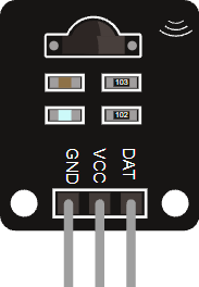
In this setup, the pins are GND, VCC, and OUT. The output pin is usually read on an analog input such as A0.
Pin Role
VCC powers the module, GND completes the circuit, and OUT carries the sensor signal back to the Arduino.
When you wire it correctly, the Arduino can sample the signal and decide whether it should light an LED, log a beat, or show a pulse value on Serial Monitor.
Code
This example reads the raw sensor signal and turns the built-in LED on when the value goes above a simple threshold. It is a good first step before moving on to full BPM detection.
In a real project you would tune the threshold after checking the raw values. Some sensors also work better with a pulse-detection library, especially if you want a cleaner beat count instead of a simple on and off response.
How The Code Works, Part By Part
Let's break the sketch into smaller steps so the signal flow is easier to follow.
Setup
The setup block prepares the LED and starts Serial Monitor. Serial is useful because it lets you see the raw sensor value while you tune the project.
Read Signal
The Arduino samples the OUT pin using analogRead(). That gives a number you can compare, store, or print while you test the sensor.
Print Signal
Printing the signal is a simple way to understand what the sensor is doing before you try to detect beats. If the values jump too much, the placement or threshold may need adjustment.
Compare And React
The code compares the raw signal against a threshold. When the value rises above that point, the LED turns on. When it drops below the threshold, the LED turns off again.
Repeat
The short delay keeps the signal readable while the loop continues sampling the sensor at a steady pace.
Wrapping Up
The Heart Monitor is a good starting point for pulse-based Arduino projects because it gives you a real sensor signal that reacts to your fingertip or earlobe.
Once you understand the raw output, you can move on to beat detection, BPM display, or a more advanced library like PulseSensor Playground for richer heart-rate projects.