This article is a guide about the KY-040. We will explain how it works, show how to wire it to an Arduino, and walk through a simple example you can use in your own projects.
The KY-040 is useful when a project needs a knob that can turn left, turn right, and also be pressed like a button.
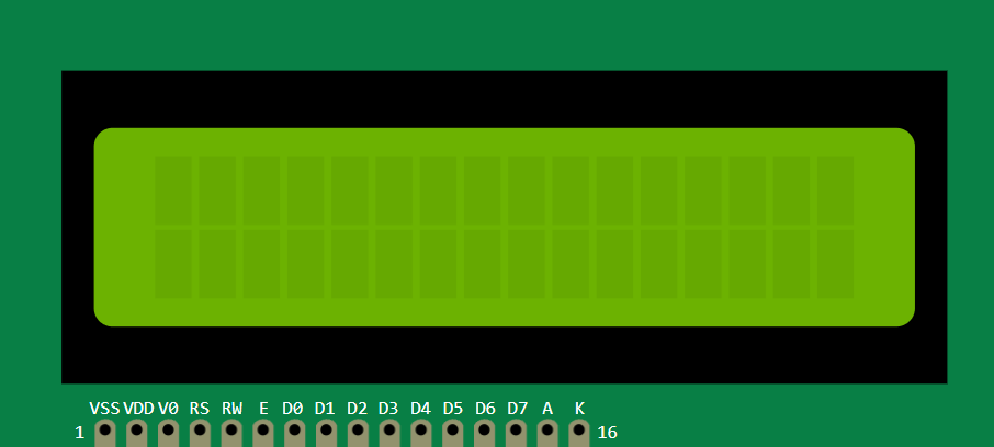
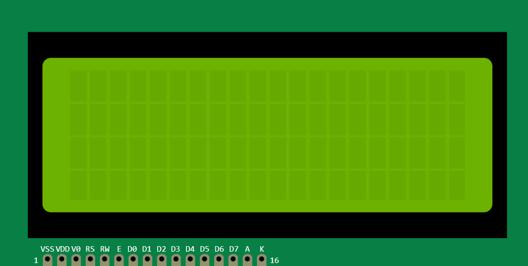
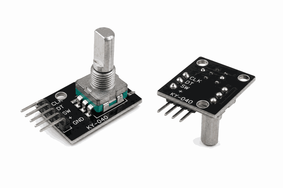
Description
The KY-040 is a rotary encoder module. Unlike a potentiometer, it does not give a fixed analog position. Instead, it produces rotation pulses that the Arduino can count, which makes it ideal for menus, counters, and value selectors.
The pushbutton on the knob adds another layer of control. You can rotate to change a value and press the knob to confirm it, which is why the module feels very natural in user interfaces. It is the kind of input that makes a menu feel calm and predictable instead of jumpy.
KY-040 vs Potentiometer
The KY-040 and a potentiometer may look similar because both are often used as knobs, but they do different jobs. A potentiometer gives a steady analog position, while the KY-040 gives step-by-step rotation pulses. That small difference changes how the Arduino reads them and how the interface feels to the user.
A potentiometer is best when you want a direct value, like brightness or volume, where the knob position should map to a fixed range. The KY-040 is better when you want menu navigation, counters, or option selection, because each click-like movement can be counted cleanly without worrying about absolute position.
| Part | Best for | How it behaves |
|---|---|---|
| KY-040 | Menus, selectors, counters | Sends rotation pulses and a pushbutton signal |
| Potentiometer | Brightness, speed, analog control | Outputs a smooth analog voltage position |
| KY-040 button | Confirm or select | Lets you press the knob after rotating it |
Use a potentiometer when the value should feel continuous. Use the KY-040 when the user should move step by step and click to confirm.
Features
Here are the main things to know about the KY-040:
| Feature | What it means |
|---|---|
| Quadrature output | Uses two pulse pins to detect rotation direction. |
| Integrated button | The knob can be pressed like a switch. |
| Digital interface | The Arduino reads pulses, not an analog voltage. |
| Menu friendly | Good for changing values, options, or modes. |
| Simple wiring | Usually needs VCC, GND, CLK, DT, and SW. |
The useful part is that the module gives you both motion and confirmation input in one part.
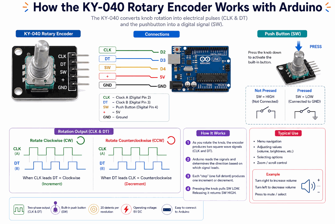
How Does It Work?
When you turn the knob, the encoder produces pulses on CLK and DT. The order of those pulses tells the Arduino which direction you turned. If CLK changes first, the rotation is one way; if DT changes first, it is the other way.
When you press the knob, the SW pin closes to ground like a pushbutton. That lets the same module act as both a rotary input and a click-to-select button.
In the simulator, turning the knob generates these pulse patterns so you can practice reading the encoder like a real menu controller. Once you understand the pulse order, the knob becomes much easier to use for scrolling values and confirming choices. If the order is read the wrong way, the menu feels backwards, which is usually the first sign that the CLK and DT pins need to be swapped.
Arduino With KY-040
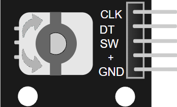
The module uses five pins: VCC, GND, CLK, DT, and SW. Connect the power pins first, then use two digital pins for the encoder signals and one digital pin for the button.

Pin Connection
Powers the encoder module so the signals can be read correctly.
Gives the encoder and Arduino the same electrical reference.
First rotation signal used to detect movement direction.
Second rotation signal used with CLK to determine direction.
Button input that closes when the knob is pressed.
The rotation pins usually work well with pull-up logic, and the switch pin can be read using INPUT_PULLUP. That keeps the wiring simple while still making the encoder easy to detect in code.
Code
This example counts rotation steps and prints the direction to Serial Monitor. It also reads the built-in button so you can confirm a press. The code matches the circuit preview, so the pin numbers line up with the wiring you see above.
The sketch keeps track of a position counter so you can see how many steps the knob has moved. In a real menu, that counter could choose a setting, scroll a list, or change a numeric value. That is also why the encoder feels nicer than a simple button when you want the user to move through options one step at a time.
How The Code Works, Part By Part
Let's break the sketch into smaller pieces so the flow is easier to understand and easier to modify later.
Setup
The setup block defines the pins and starts the serial monitor. This is where the Arduino gets ready to read the encoder pulses and the switch press.
Read Rotation
This part watches the CLK pin for a state change. When it changes, the code checks DT to find the direction and updates the position counter.
Read The Button
The pushbutton is handled separately. Because the switch is active-low, the sketch checks for LOW to know when the knob has been pressed.
Repeat
The loop keeps watching the encoder so the Arduino can react to every turn and press. That is what makes the module feel responsive in menus and selector-style interfaces.
Wrapping Up
The KY-040 is a very handy input module when you want a knob that can scroll values and also act like a button. It is easy to wire and very useful for interactive Arduino interfaces.
Once you understand the pulse direction and the button pin, you can build cleaner menu systems and value controls with very little code. That makes the encoder a nice fit for projects where the user needs to move through options one step at a time, instead of typing numbers or pressing a long row of buttons.
It is also a good part to learn early because the same idea shows up in many interface projects. The knob gives you a smooth way to browse, adjust, and confirm choices without making the code feel heavy or complicated. In a small dashboard, that usually feels more polished than a pile of separate buttons.