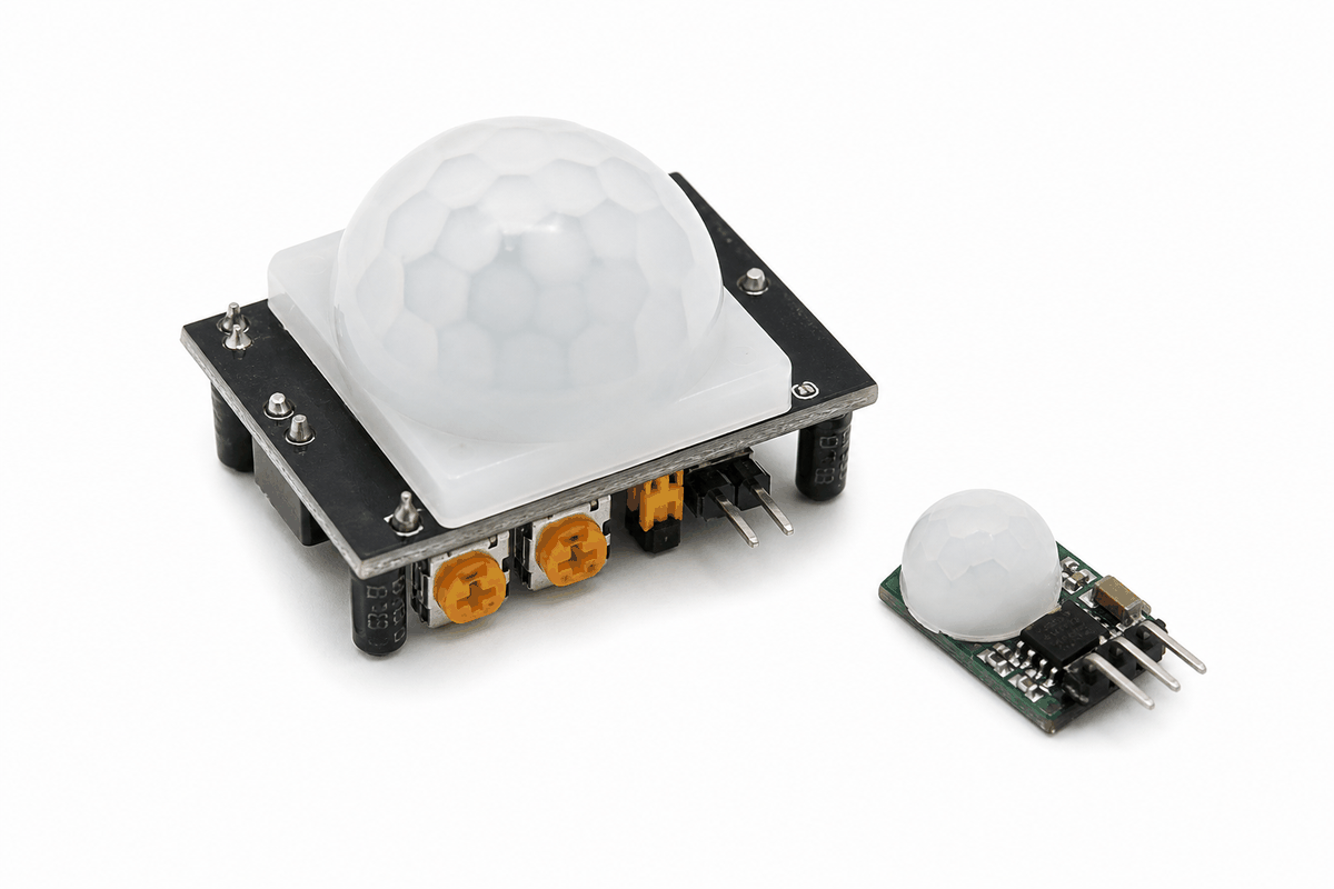
This article explains the PIR Motion Sensor in a practical way: how it detects motion, how to wire it to Arduino, and how to read the digital output.
PIR sensors are common in motion lights, alarm systems, and room-occupancy projects, so they are worth understanding early.
Description
A PIR sensor does not measure movement directly like a motor or an encoder. Instead, it watches for changes in infrared energy from people, animals, or other warm objects moving across its field of view. That is why it is called a Passive Infrared sensor: it listens for changes without sending out its own signal.
For beginners, this makes the module feel simple to use. The Arduino only needs to read a digital output, while the sensor handles the detection work on its own. When motion is detected, the OUT pin goes HIGH for a short time, which gives the sketch an easy on/off signal to react to.
Features
Here are the main things to know about the PIR Motion Sensor:
| Feature | What it means |
|---|---|
| Passive infrared sensing | Detects changes in infrared heat, not visible light. |
| Digital output | OUT goes HIGH when motion is detected. |
| Easy wiring | Usually only needs VCC, GND, and OUT. |
| Delay control | The output can stay HIGH for a few seconds after motion is seen. |
| Retrigger behavior | Can keep extending the HIGH time if motion continues. |
| Warm-up time | Needs a short settling period after power is applied. |
| Digital trigger | Great for LEDs, alarms, and relay control. |
The useful part is that the module gives the Arduino a clean HIGH or LOW signal, so you can turn on a light, buzzer, relay, or serial message without complicated code.
That clean digital behavior is why PIR modules show up so often in hallway lights and occupancy detection projects. You do not need to measure a value and decide what it means. The sensor already does the motion decision for you.
How Does It Work?
The PIR sensor uses a sensing element that reacts to changes in infrared energy. When a warm body moves across the sensor's view, the output circuitry notices that change and raises the OUT pin. The Arduino then reads that HIGH signal and treats it as motion.
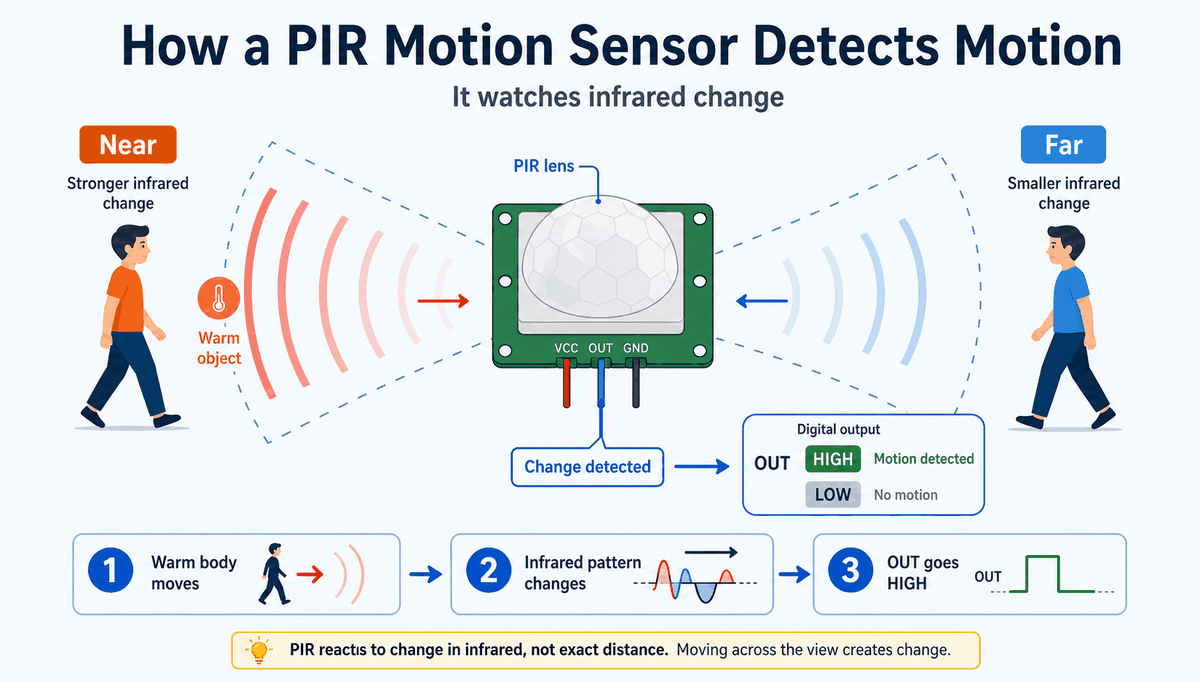
The module drives OUT HIGH for a short delay, then returns it to LOW. That behavior matches the real idea of a PIR sensor: a motion event produces a digital pulse the sketch can react to.
The sensor usually needs a short warm-up period after power is applied. Once it settles, it becomes much more reliable for motion detection. This is why real PIR projects often wait a few seconds before trusting the first reading.
Arduino With PIR Motion Sensor
This circuit preview shows a PIR sensor connected to an Arduino Uno with an LED response. It is a simple starting point because the sensor gives a digital signal, and the LED makes that signal easy to see.

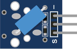
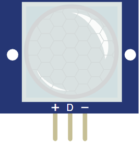
Pin Connection
The PIR sensor uses three pins: VCC, OUT, and GND. The table below shows the wiring used in the circuit preview and why each line matters.
Powers the PIR module so the sensing circuit can work.
Sends the HIGH or LOW motion signal into Arduino.
Gives the sensor and the Arduino the same electrical reference.
Because the signal is digital, you do not need analog pins or conversion math. That makes the wiring and the code approachable for beginners. If your project also uses an LED or relay, the PIR output can trigger that part directly.
Code
This example reads the PIR output and turns the built-in LED on when motion is detected. It is a simple pattern, but it shows the full sensor flow clearly.
The sketch keeps checking the sensor in a loop, so the LED follows the motion state in real time. In a real project, you could replace the LED with a relay, buzzer, or message display instead.
How The Code Works, Part By Part
Let's break the sketch into smaller pieces so the motion flow is easier to understand and modify later.
Setup
The setup block defines the PIR input pin, the LED output pin, and opens Serial Monitor. This is where the board gets ready before it starts watching for motion.
Read Motion
This part checks the PIR output with digitalRead(). A HIGH value means motion is present, while LOW means the sensor is idle.
React To Motion
Here the sketch decides what to do when motion is detected. The LED turns on and a message is printed, which makes it easy to test the sensor while learning.
Repeat
The loop keeps running so the sensor is always watched. That is what makes the PIR useful for continuous motion detection in a real project.
Wrapping Up
The PIR Motion Sensor is a good part when you want Arduino to respond to movement in a room or near a device. It is simple to wire, simple to read, and easy to combine with LEDs, buzzers, and relays.
Once you understand how the OUT pin behaves and how the warm-up period affects the first reading, you can use the sensor confidently in motion lights, alarms, and occupancy projects.
It is a small module, but it teaches a useful idea: a sensor can watch for change and turn that change into a digital signal that your sketch can act on immediately.