This article is a guide about the Rotary Dialer. We will explain how it works, how the pulse signal is generated, how to wire it, and how to count the pulses in Arduino code.
The Rotary Dialer is useful when a project needs a physical input that feels different from a normal button or knob.
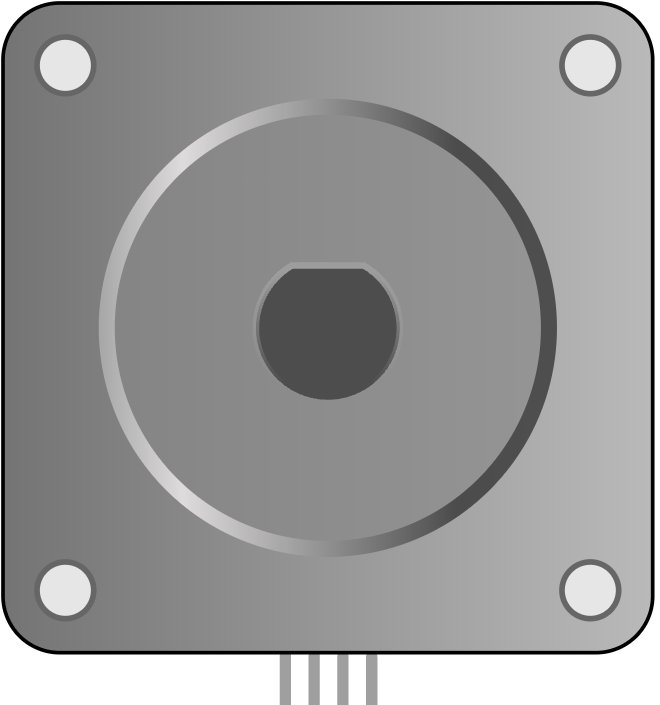
Description
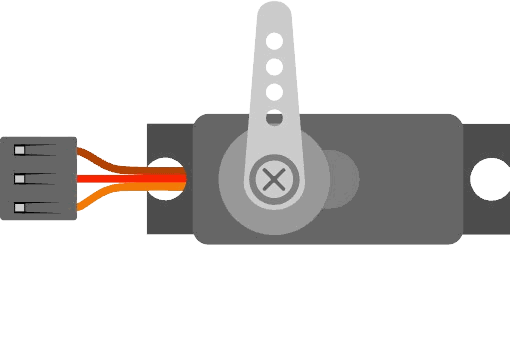
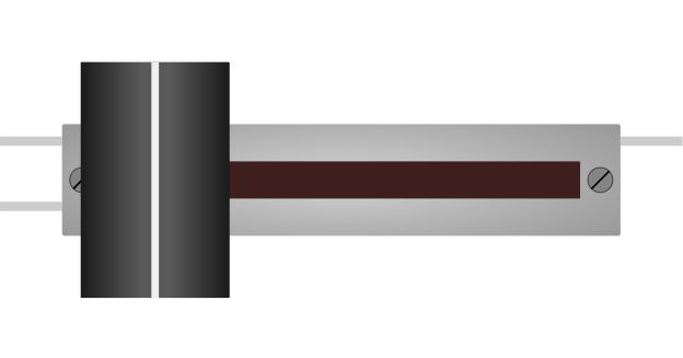
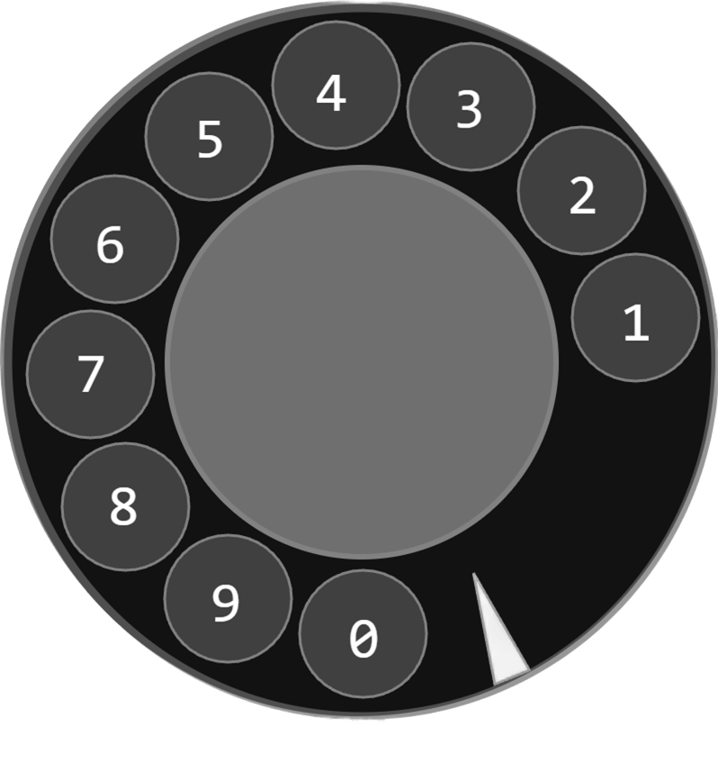
The rotary dialer is a classic telephone-style input device. When you rotate the dial and release it, the mechanism returns to its resting position and produces a series of pulses that represent the number you dialed.
That makes it a great learning part for pulse counting, state-change detection, and older-style input logic. Instead of giving the Arduino a smooth analog value, the dial gives a countable sequence of on/off events that the code can turn into a digit.
In the simulator, the rotary dialer exposes a dial state and a pulse output, which makes it easy to see both the start and the count of a dial action.
Features
Here are the main things to know about the Rotary Dialer:
| Feature | What it means |
|---|---|
| Pulse output | Produces a pulse train that can be counted in code. |
| Dial state | Shows when the dial is being moved and released. |
| Old-school input feel | Useful for learning event counting instead of analog reading. |
| Beginner friendly | Good for practicing state changes and debouncing ideas. |
| Interactive | Lets the user enter a digit by rotating the dial. |
The most important feature is that the dial turns a physical motion into a digit-sized pulse count.
How Does It Work?
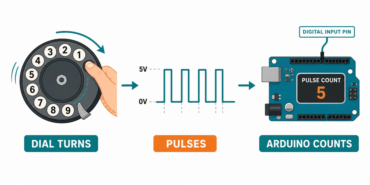
When you rotate the dial, it stores the movement mechanically and then returns to its resting position. During that return, the contact repeatedly opens and closes, creating a pulse pattern that the Arduino can count.
The dial contact is usually held at one state while the dial is moving, then it produces a series of pulses as it comes back. The number of pulses matches the number you selected, so the sketch can count them and recover the dialed digit.
This is why rotary dial projects are a nice introduction to input timing. The Arduino is not reading a steady value. It is watching a sequence of transitions and counting them carefully.
Pulse Counting
The pulse line changes state several times while the dial returns. The sketch watches for those state changes and increments a counter each time the correct transition appears.
State Change Detection
State-change detection is useful here because it lets the Arduino count only when the pulse actually changes. That keeps the digit count stable instead of counting the same pulse many times.
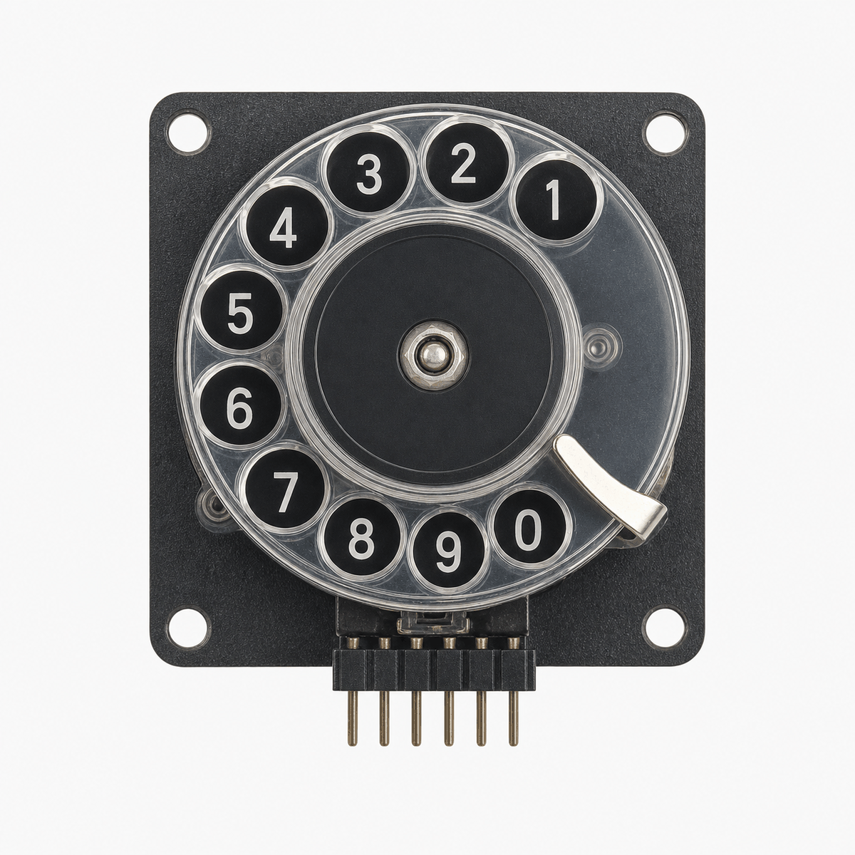
Arduino With Rotary Dialer
This circuit preview shows the rotary dialer connected to an Arduino Uno so you can read the dial state and count the pulse line. It is a good example of a mechanical input because the hardware motion becomes a digital number in code.

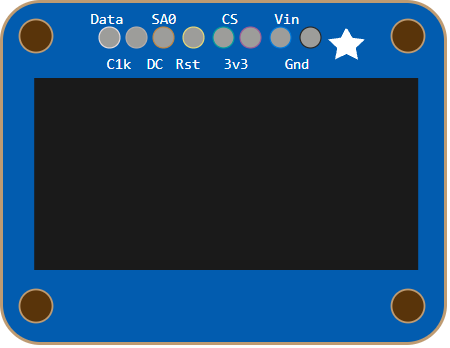
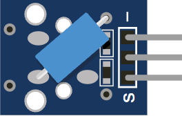
Pin Connection
The pin map below matches the circuit preview. The dial pin marks when a number starts and ends, while the pulse pin carries the count that becomes the digit.
Signals the start and end of a dial action.
Carries the pulse count that the sketch measures.
Shares the ground reference with the Arduino.
With this wiring, you do not need an analog pin or a special driver. The Arduino just watches the changing states and turns them into a number.
Code
This example counts the pulses from the rotary dial and prints the digit to Serial Monitor when the dial returns to rest.
Once the count works, you can use the dial to select a menu item, enter a number, or trigger a specific action in your project.
How The Code Works, Part By Part
Let's break the sketch into smaller pieces so the flow is easier to understand and easier to modify later.
Pin Setup
The sketch starts by setting the dial and pulse pins as inputs with pull-ups. That lets the Arduino read each contact cleanly while the dial moves.
Track State
The code stores the previous dial and pulse states so it can tell when a new change happens. This is the key idea behind pulse counting.
Count Pulses
Every time the pulse line changes to the active state, the sketch adds one to the counter. That counter becomes the dialed digit after the dial returns home.
Finish Dial
When the dial state changes back, the sketch knows the number entry is complete and prints the digit.
Wrapping Up
The Rotary Dialer is a fun input part when you want to learn pulse counting and state-change detection with a real mechanical feel.
Once you understand the dial state, the pulse line, and the counting loop, you can use the module confidently in number input demos and retro-style projects. It is a small part, but it teaches a useful habit: watch the timing, not just the final state.