Think of a breadboard like a reusable LEGO base for electronics: you can plug parts in, move them around, and try ideas fast - without soldering.
The only tricky part is that the holes are not all connected. Once you understand which holes share the same metal strip underneath, a breadboard becomes one of the easiest tools for learning wiring.
Description
A breadboard is a plastic block with a grid of holes. Under the plastic are springy metal clips. When two holes share the same metal clip, they are electrically connected - like they are already wired together.
This simulator's breadboard is a small 17-row style board. It has a center gap and four power rails: top minus (T-), top plus (T+), bottom plus (B+), and bottom minus (B-).
Features
| Feature | Why it matters |
|---|---|
| Solderless connections | Fast to build and easy to change while learning. |
| 5-hole terminal rows | Perfect for joining a few leads together (like a wire, a resistor leg, and an LED leg). |
| Center gap | Lets DIP chips sit across the gap so the two sides don't short together. |
| Power rails (T+/T-/B+/B-) | Gives you a simple way to distribute 5V/3.3V and GND. |
How the Holes Connect
A breadboard has two connection zones:
1) Terminal strips (the main grid)
Each numbered row is split into two groups of five holes because of the center gap.
- Left group:
10A,10B,10C,10D,10Eare connected together. - Right group:
10F,10G,10H,10I,10Jare connected together. - Across the gap:
10Eis not connected to10Funless you add a part (like a resistor) bridging the gap.
This is why beginners place a DIP chip across the gap: pins on the left side land in A-E, and pins on the right side land in F-J, keeping them separated.
2) Power rails (the long rails)
The rails are long columns meant for power distribution:
T+andT-run along the top edge.B+andB-run along the bottom edge.
On this simulator breadboard, each rail is continuous end-to-end (for example T+1 is connected to T+17). On some real breadboards, rails can be split in the middle, so it's a good habit to check with a continuity test.
Common Beginner Mistakes
- Forgetting GND: your circuit needs a return path. Without ground, signals don't have a reference and things act strange.
- LED in the same row: if both LED legs land in one connected 5-hole row, the LED gets shorted and won't behave correctly.
- Assuming rails are connected: left/right rails might not be connected on larger breadboards. Bridge them with a jumper if you need the same power on both sides.
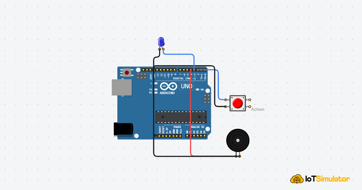
Demo: Use a Breadboard to Blink an LED
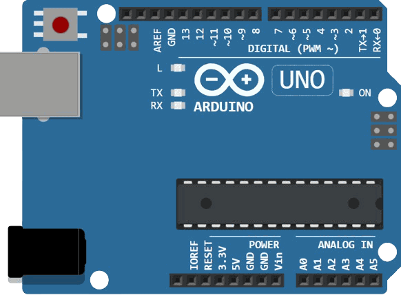
This mini build shows both concepts at once: the terminal row is used to join Arduino pin 13 to a resistor, and the power rail is used as a convenient ground bus.
Arduino Uno pin 13 drives an LED through a resistor. The breadboard row makes the connection easy, and the rail keeps GND tidy.

If the LED does not light up, check two things first: (1) the LED direction (A goes to the resistor, C goes to GND), and (2) that you used the same numbered row (for example 10A to 10E are connected, but 11A is a different row).
Wrapping Up
A breadboard is simple once you memorize the rule: rows connect in groups of five, and rails connect in long lines. After that, most wiring mistakes become easy to spot and fix.
When you build your next circuit, start by choosing a ground rail, bring GND to it once, and then reuse that rail everywhere. Your wiring stays cleaner and you spend less time debugging.