This article is a guide about the Big Sound Sensor module. We will walk through what it detects, how the analog and digital outputs behave, and how to wire it to an Arduino Uno so you can actually use it in a real project.
If you want to build a clap switch, a noise alarm, or any simple reaction system that responds to loud sound, this module gives you an easy starting point. It turns changes in room noise into a signal the Arduino can read, which makes it much easier to trigger an LED, buzzer, or other output.
By the end of this guide, you will know which pin does what, how to read the changing value in Serial Monitor, and how to tune the sensor when the room is too quiet, too noisy, or somewhere in between.
Description
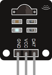
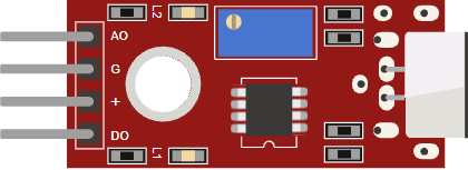
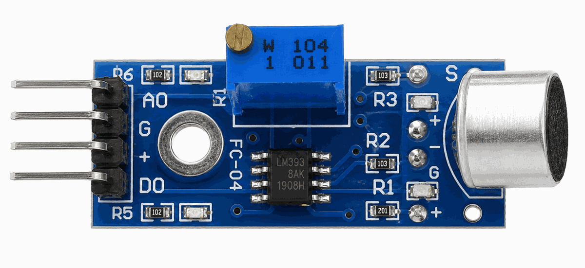
Some versions of this module use a blue PCB instead of red. The layout stays the same, so the board is easy to recognize even when the color changes.
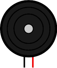
The Big Sound Sensor turns sound activity into an electrical signal that the Arduino can read. In simple terms, the microphone picks up vibration in the air, and the board turns that into a signal that changes as the room gets louder or quieter.
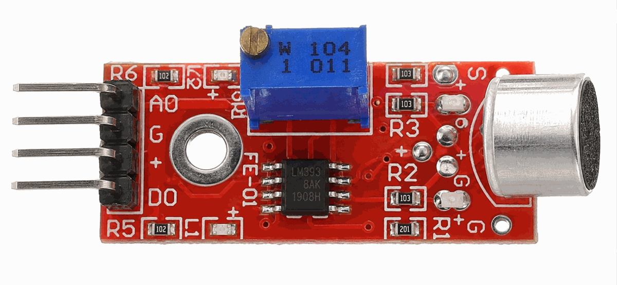
Many versions of this module use an electret condenser microphone with an LM393 comparator stage. That is the useful part to remember: the microphone captures the sound change, and the comparator helps turn that change into a clean digital trigger when the level crosses the threshold.
Most versions of this module give you two useful outputs. AOUT lets you watch the sound level as a changing value, while DOUT gives you a simpler on or off trigger when the sound crosses a set threshold. The red breakout style, blue trimmer, and metal microphone can make it easy to spot on a crowded breadboard.
Features
Here are the main things to know about the Big Sound Sensor:
| Feature | What it means |
|---|---|
| Electret microphone | Captures room sound and turns it into a small electrical signal. |
| LM393 comparator | Compares the microphone signal against a threshold for digital triggering. |
| Analog envelope output | Shows a changing sound level on AOUT. |
| Digital threshold output | Switches DOUT when the signal crosses the set level. |
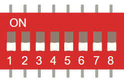
| Adjustable sensitivity | A small trimmer changes how easily the module reacts. |
| 3.3V to 5V supply range | Many KY-038 style modules run from common Arduino voltages. |
| Indicator LEDs | Power and trigger LEDs help you see module activity at a glance. |
| Simple wiring | Usually needs power, ground, and one or two signal connections. |
The important part is that the module gives you a practical sound signal, not an exact decibel meter. That makes it good for quick experiments and beginner Arduino projects where a sound event matters more than perfect audio measurement. It is also why the board is easier to use as a trigger than as a measurement tool.
How Does It Work?
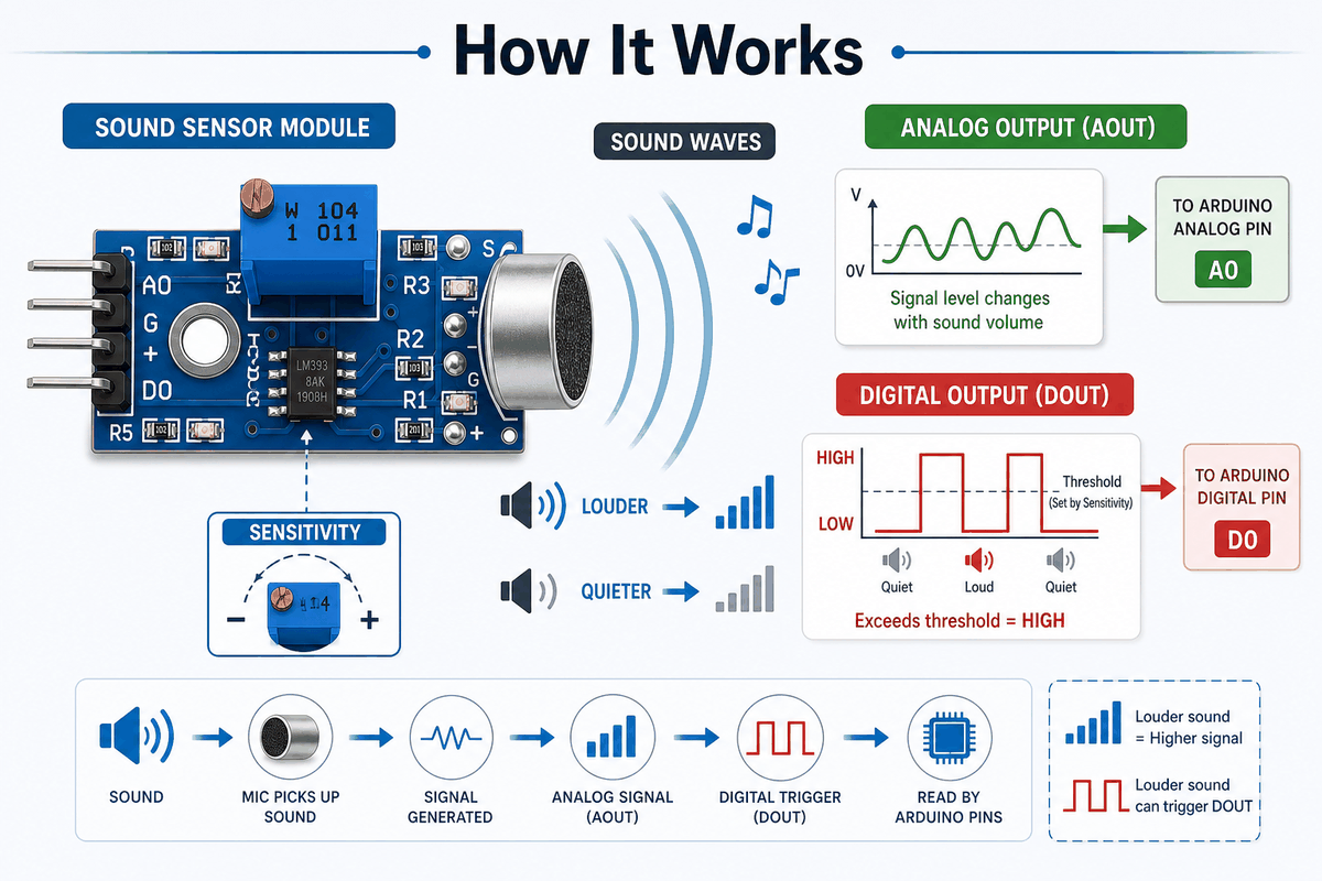
The microphone part reacts to sound waves in the room and produces a changing electrical signal. The board then sends that signal to the Arduino through the analog output, or compares it against a threshold and produces a digital trigger. In other words, the same sound gets turned into two different kinds of information.
That means you can use the sensor in two different ways. The analog path is better when you want to watch the sound level trend over time. The digital path is better when you only care whether the sound passed a chosen limit.
Many modules also include a small potentiometer so you can change the sensitivity. This matters in real use because a sensor placed near a speaker behaves very differently from one placed across the room.
Sound To Signal
The first step happens at the microphone. It picks up vibration in the air and turns that movement into a small electrical signal. That signal is the raw starting point for both outputs.
Analog Output Path
The analog value is a better fit when you want to watch sound movement over time. It gives you a changing reading that follows louder and quieter sound, which is useful when you want to log or compare levels instead of only reacting to them.
Digital Trigger And Sensitivity
The digital output is a better fit when you want a simple event, like a clap turning on a light or a loud sound triggering a buzzer. The room itself affects the reading. Soft furniture, distance from the source, and background noise all matter. If the threshold is too low, the output can flicker on normal room noise. If it is too high, even a clap may be missed. That is why the module often needs a little calibration before it feels reliable in a real project.
Limitations And Tradeoffs
The Big Sound Sensor is helpful, but it has a few limits that beginners should know about before they trust it too much.
| Tradeoff | Why It Matters |
|---|---|
| Not a recording device | The sensor tells you that sound happened, but it does not capture voice or music like an audio recorder. |
| Room conditions change the result | Noise, distance, and furniture can change how the module reacts, so the same threshold may not work everywhere. |
| DOUT needs tuning | If the threshold is too low, the output flickers; if it is too high, even a clap can be missed. |
| AOUT is relative, not exact | The analog output is useful for comparison, but it should not be treated like a calibrated sound meter. |
Not a recording device: The sensor can tell you that sound happened, but it is not the same as capturing voice or music. The reading is better treated as a loudness signal than a clean audio stream.
Values depend on the room: A quiet room, a crowded room, and a room next to a speaker will all produce different behavior. In practice, that means the same threshold may work one day and feel wrong in another space.
DOUT needs tuning: If the threshold is set too close to the background noise, the digital output can bounce around and feel unstable. When that happens, the fix is usually to turn the trimmer a little and test again.
AOUT is useful, but not exact: The analog output is great for watching change, but it should not be treated like an absolute sound meter. It is more useful for relative comparison than for measuring exact loudness.
Arduino With Big Sound Sensor
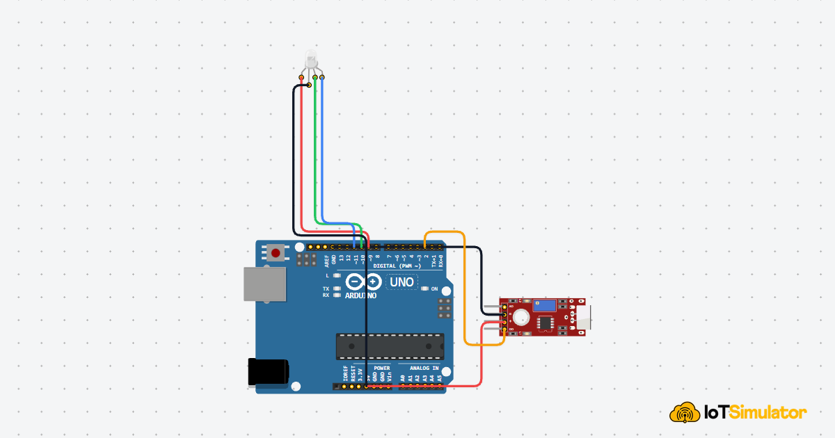
The preview below shows a simple Arduino Uno setup so you can see the Big Sound Sensor in context before looking at the code. The analog and digital outputs go to different pins, which makes it easier to understand how one sensor can give you both a live reading and a simple trigger.

The sensor uses four pins in this setup: VCC for power, GND for ground, AOUT for the analog sound level, and DOUT for the threshold trigger. Many beginner projects only need one output, but keeping both in the circuit helps you compare the raw reading and the simple on-off response.
Pin Connection
For the Arduino Uno, this connection is simple: power the module, share ground, then use one analog pin for the changing sound level and one digital pin for the threshold trigger. The table below shows the exact wiring and why each line matters.
Powers the sensor board so the microphone and comparator can work.
Gives the sensor and the Arduino the same electrical reference.
Sends the changing analog sound level for reading in code.
Sends a simple HIGH or LOW trigger when the sound crosses the threshold.
AOUT is the pin to use when you want to watch the sound level change over time in Serial Monitor. DOUT is the pin to use when you only care about an event, like a clap, knock, or sudden loud noise.
The shared ground connection is important. If the sensor and the Uno do not share ground, the signal can look unstable or stop reading correctly. Once the wiring is right, the trimmer becomes the last tuning step: turn it one way to make the sensor more sensitive, or the other way to make it ignore background noise.
Code
This example reads both the analog and digital outputs, then turns the built-in LED on when the sound level crosses a threshold. It is a better first sketch because it shows the raw reading, the trigger output, and the project response in one place.
Once this works, you can swap the LED for a buzzer, relay, or other output. If the sensor reacts too often, raise the threshold or turn the trimmer until the background noise stops triggering it.
How The Code Works, Part By Part
Let's break the sketch into smaller pieces so the flow is easier to understand and easier to modify later.
Setup
The setup block prepares the input, output, and Serial Monitor. This lets you watch both sensor readings while the board waits for sound.
Read Signal
Here the sketch reads both signals from the module. The analog value changes with sound strength, while the digital value shows whether the board thinks the sound passed the threshold.
Print Value
Printing both values helps you compare the raw sound level with the module's trigger output. That makes it easier to decide whether the threshold is too low or too high.
Repeat
The short delay keeps the serial output readable while the sketch continues checking the sensor and updating the LED response.
Wrapping Up
The Big Sound Sensor is a practical module when you want Arduino to react to sound instead of measuring audio in a precise way. In this article, you saw that the board gives you two useful outputs: AOUT for watching the sound level change, and DOUT for getting a simple trigger when the noise passes a threshold.
The wiring is just as important as the code. VCC powers the module, GND keeps the reference shared with the Arduino Uno, AOUT connects to an analog pin like A0, and DOUT connects to a digital pin like D2. Once those connections are correct, the trimmer becomes the last piece of the setup because it controls how easily the sensor reacts to background noise.
That is why this module works well for clap switches, noise alarms, simple LED reactions, and other beginner projects that only need to know whether sound happened. If the sensor feels too sensitive, raise the threshold or adjust the trimmer. If it feels too quiet, lower the threshold and test again. After a little tuning, the sensor becomes much easier to trust in real use, and the same wiring pattern can be reused in many small Arduino projects.