This article is a guide about the Flame Sensor module. We will explain what it detects, how the infrared sensing works, how to wire the module, and how to read it from Arduino code.
Flame detection projects are a good example of how a small sensor can turn a physical event into a simple value that a sketch can understand.
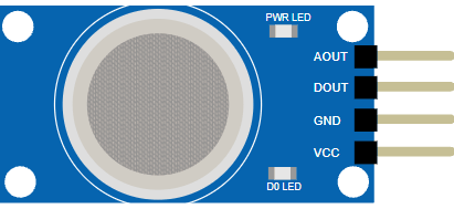
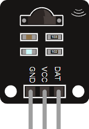
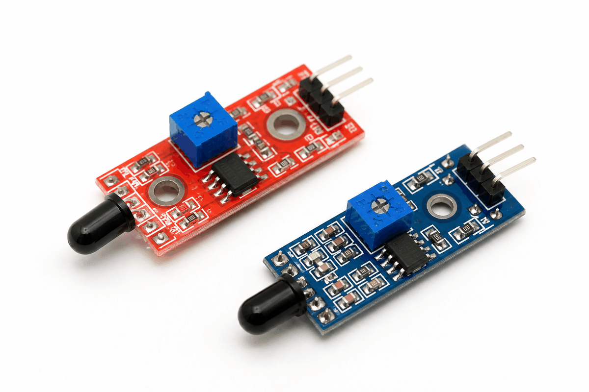
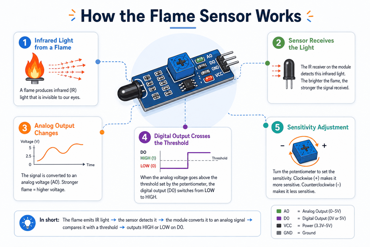
Before we jump into the description, it helps to look at the real module first so the shape, the sensor head, and the sensitivity knob are easier to recognize.
Description
The Flame Sensor module is built to detect infrared light emitted by flames. In many versions, the board uses an infrared receiver and a comparator circuit so the Arduino can read both a changing analog signal and a threshold-based digital signal.
That makes the module useful in beginner fire-alert projects, robot safety demos, and simple alarm systems. It is not a replacement for a certified fire-safety device, but it is excellent for learning how an embedded system can notice an environmental condition and react to it.
Many KY-026 style flame modules are sensitive to a wavelength range around 760 nm to 1100 nm and include a small potentiometer for sensitivity adjustment. That means the module can be tuned for different room conditions, distances, and flame sizes, which is helpful when you want more stable readings.
Features
Here are the main things to know about the Flame Sensor:
| Feature | What it means |
|---|---|
| Infrared detection | Looks for light in the flame-sensitive infrared range. |
| Analog output | Lets you watch the signal level and tune sensitivity in code. |
| Digital output | Provides a simple threshold-based trigger for alarm-style projects. |
| Adjustable sensitivity | A small onboard trimmer changes how easily the module reacts. |
| Fast response | Useful when the sketch needs to react quickly to flame presence. |
| Simple wiring | Usually only needs power, ground, and one or two signal lines. |
Because the module can expose both an analog value and a digital trigger, it is flexible enough for debug, testing, and beginner safety alerts.
How Does It Work?
The sensor sees infrared light that is commonly produced by flames. The receiving part converts that light into an electrical signal, and the board then conditions that signal so the Arduino can read it reliably.
The analog side is useful when you want to observe how strong the flame signal is. The digital side is useful when you only care whether the signal crossed a chosen threshold.
That threshold is set by the onboard potentiometer on many flame sensor modules. Turning the trimmer changes how sensitive the module is, so the digital output can switch earlier or later depending on the environment.
Ultraviolet (UV) Detection
UV flame detectors are a different class of sensor from the common Arduino flame module.
They watch ultraviolet light in the flame-emission range. Commercial UV flame sensors, such as Hamamatsu's UVTRON series, are designed to respond only to UV wavelengths around 185 nm to 260 nm.
That makes them useful in safety systems where the detector must react quickly to flame radiation and ignore ordinary visible light.
Flame Detector Infrared (IR)
The typical Arduino flame sensor module is an infrared detector. Product datasheets for these modules usually describe a sensitivity range around 760 nm to 1100 nm, which matches the near-infrared light that flames emit. This is the version most beginners meet first because it is cheap, easy to wire, and works well for simple flame-detection demos.
Ultraviolet/Infrared (UV/IR) Detection
UV/IR flame detectors combine both sensing methods in one unit.
The UV channel watches for ultraviolet flame radiation while the IR channel looks for infrared energy.
The detector compares both signals to reduce false alarms from sunlight, reflections, or warm objects. That is why UV/IR devices are more common in industrial fire detection than in small hobby modules.
Analog Vs Digital Output
Analog output gives you a wider range of values, which is better when you want to experiment or log readings.
Digital output gives you a clean on/off response, which is better for alarms, indicators, and simple automation rules.
Reading Notes
The reading can change with distance, angle, background light, and the size of the flame.
For that reason, flame sensor projects usually work best when the sensor is aimed carefully and the code uses a small amount of filtering or threshold checking.
Arduino With Flame Sensor
The Arduino setup is straightforward because the module gives you both an analog reading and a digital trigger. That means you can start with a simple serial test first, then move to a warning LED or buzzer once the signal looks stable.
In a small fire-alarm demo, the analog line is handy for calibration while the digital line is handy for the final reaction. That makes the same module useful in both learning mode and real project mode.

Pin Connection
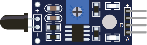
The connection map tells you which pins matter most when wiring the module to an Arduino. Match power, ground, and the signal pins carefully so the circuit behaves the way the sketch expects.
On this module, VCC powers the board, GND is the ground reference, DOUT gives a threshold trigger, and AOUT gives the analog signal level.
Powers the sensor board and its comparator circuit.
Shares the electrical reference with the Arduino.
Sends the changing analog flame level for calibration and logging.
Sends a simple trigger when the module crosses the threshold.
AOUT is useful when you want to watch changes in the flame signal. DOUT is useful when you want a simple trigger that can turn on an LED, buzzer, or alarm state.
Code
This example reads both outputs from the circuit preview so you can see how the topology works in practice. AOUT goes to A0 for the changing flame level, while DOUT goes to D2 for the threshold trigger. No external library is needed here because the module already gives a plain analog voltage and a simple digital output, so the Arduino can read it directly with analogRead() and digitalRead(). That keeps the first test sketch short, easy to debug, and focused on the sensor behavior instead of a library setup.
Once the raw value looks reasonable, you can use the threshold to decide when the sensor should trigger a warning or alarm. In this layout, the analog pin is useful for calibration and the digital pin is useful for the final reaction, so the same sketch helps you understand both parts of the module at once.
How The Code Works, Part By Part
Let's break the sketch into smaller pieces so the flow is easier to understand and easier to modify later.
Setup
The setup block prepares Serial Monitor and sets the digital pin as an input. That gives you a live window for checking how the flame signal changes while you move the sensor around, and it keeps the digital trigger ready for use if the module crosses the threshold.
Read Signal
Here the sketch reads the analog voltage and the digital trigger from the module. The analog value changes as the infrared light level changes, while the digital value shows whether the module thinks the threshold has been crossed.
Print Value
Printing both values makes it much easier to calibrate the sensor. You can compare the number in normal light and near a flame-like source to decide what threshold makes sense, then see whether the digital output switches the way you expect.
Repeat
The short delay keeps the serial stream readable while the sketch keeps checking the sensor in a loop. If the analog value passes the threshold or the digital pin goes HIGH, the sketch can react immediately with a message, LED, or buzzer in a bigger project.
Wrapping Up
The Flame Sensor is a practical module when you want Arduino to react to infrared light from a flame.
Once you understand the analog reading, the digital threshold, and the sensitivity adjustment, you can use the module in beginner safety demos and simple alert systems with much more confidence.
It is especially useful as a learning part because it shows a very real embedded idea in a simple way: the hardware senses a physical event, the board turns that into a number, and your code decides what to do next.
That same pattern is what you will see again and again in other sensor projects, so this module gives you a good mental model to carry forward.