This article is a guide about the KS2E-M-DC5 relay. We will explain how it works, how the coil and contacts behave, how to wire it, and how to drive it from Arduino code.
Relays are useful when a small Arduino signal needs to control a larger or separate load safely through a switch-like mechanism.
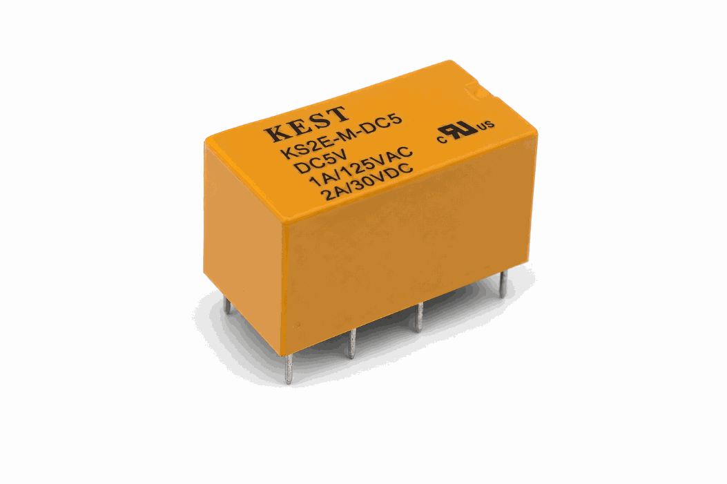
Description
The KS2E-M-DC5 is a 5V relay module. Inside the relay is an electromechanical switch with a coil and a set of contacts. When the coil is powered, the internal switch changes state and connects a different pair of terminals.
That makes the relay useful for learning how a microcontroller can control a separate circuit without directly carrying the load current. In simple projects, it is often used for turning things on and off, such as lamps, motors, alarms, or test loads.
Arduino Uno cannot use this part as a standalone power switch for the load. The board only drives the relay coil, while the device being switched still needs its own supply on the contact side. That separation is what lets the relay handle higher voltage or higher current than the Arduino could safely manage by itself.
KS2E-M-DC5 vs Common Relay
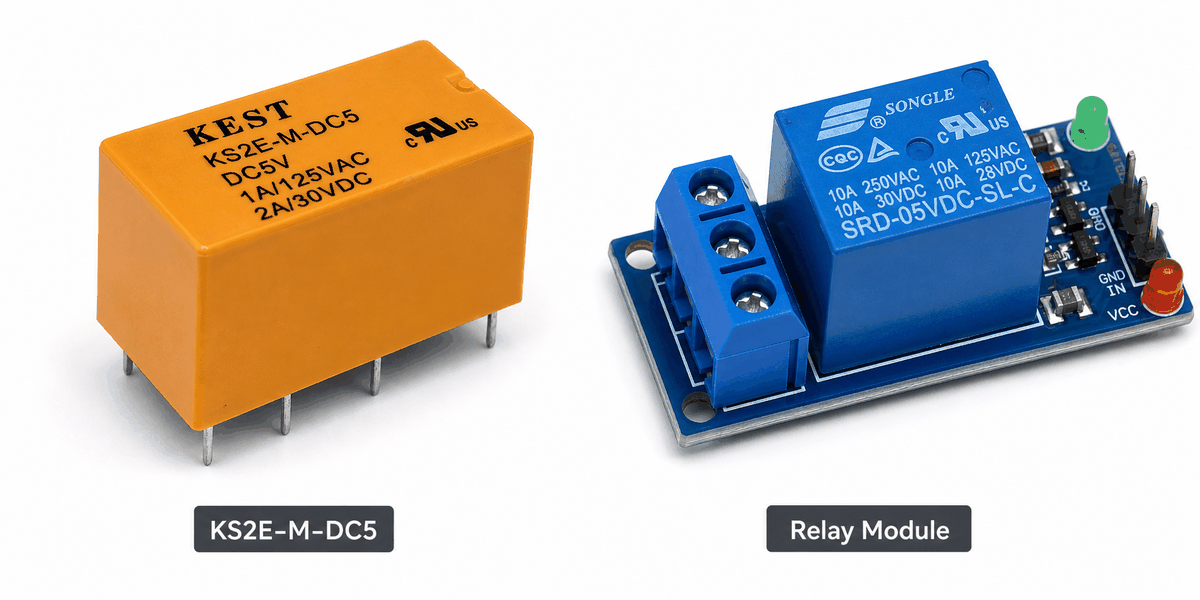
People often compare the KS2E-M-DC5 with a common relay because both parts do the same basic job: they switch a load using a low-power control signal. The difference is mostly in how the module is packaged and how much of the switching hardware is already built in.
| KS2E-M-DC5 module | Common relay |
|---|---|
| Usually shown as a complete relay module with control side and contact side | May refer to the relay block itself without a full module layout |
| Easy to pair with Arduino-style wiring and simulation | Often needs the rest of the circuit built around it |
| Good for learning coil control, NO, and NC behavior together | Useful when you only need the bare switching component |
| Matches beginner switching and automation demos well | Better when you already know the relay package you want to use |
In practice, this module is more useful for a project page because it shows the whole switching idea in one place. You can see the coil side, the contact side, and the load path together, which makes it easier to understand how the relay sits between the Arduino and the device being controlled.
Use the KS2E-M-DC5 module when you want the relay behavior and the wiring story together. Use a common relay description when you only mean the switching part itself.
Features
Here are the main things to know about the KS2E-M-DC5:
| Feature | What it means |
|---|---|
| 5V coil | The relay coil is driven with 5V-level control. |
| NO and NC contacts | Lets you switch between normally open and normally closed paths. |
| Electromechanical action | The coil moves internal contacts when powered. |
| Isolation friendly | Useful when the control side and load side should stay separate. |
| Beginner friendly | Easy to understand as a physical switch controlled by code. |
The most important idea is that the relay behaves like a controllable switch, not like a sensor.
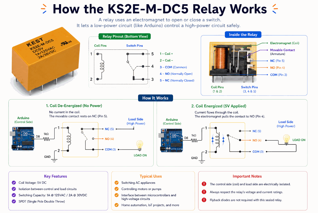
How Does It Work?
A relay uses a coil to move internal contacts. When the coil is off, the common terminal connects to the normally closed contact. When the coil is powered, the common terminal moves to the normally open contact.
That switching action is what makes the relay useful. A small Arduino output can energize the coil, and the relay can then control a separate circuit through its contact pins.
In other words, the microcontroller does not power the load directly. It only controls the relay coil, and the relay handles the switch change for the other circuit.
Coil State
When the coil is unpowered, the contacts rest in their default position. That default state matters because it tells you what the load will do before the Arduino sends any signal. If the relay is wired through NC, the load starts connected; if it is wired through NO, the load stays off until the coil pulls in.
When the coil receives power, the relay changes state and the output path switches. The transition is mechanical, so there is a tiny delay between the control signal and the contact movement. In practice, that delay is usually short enough for switching lamps, fans, alarms, and other everyday loads, but it is still a real physical movement inside the relay.
That is why relays feel different from transistors or MOSFETs. A transistor changes an electrical path directly, while a relay gives you a literal moving switch that can isolate the control side from the load side.
Contact Switching
The common terminal is the moving connection. It either links to NC in the default state or to NO when the coil is activated. That means the relay can be used either as a break-before-make style path or as a normally-open switch that only closes when the coil is energized.
This is useful when the Arduino should stay away from the load voltage. The relay contacts can handle the switching job while the microcontroller only sends a small coil signal, which keeps the control circuit simple and the high-power side separated.
In a real build, this is the part you pay attention to when choosing how the load should behave during startup or reset. If you want the device off by default, use NO. If you need the circuit alive until the relay cuts it off, use NC.
Arduino With KS2E-M-DC5
The relay is easiest to understand when you first see the control side and the switch side together. The Arduino only drives the coil, while the relay contacts handle the load path that would otherwise be too much for the microcontroller.

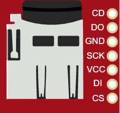
Pin Connection
The connection map tells you which pins matter most when wiring the module to an Arduino. Match the coil pins and contact pins carefully so the circuit behaves the way the sketch expects.
The Arduino output that energizes the relay coil.
Completes the coil circuit so the relay can switch.
Common terminal for the first switch group.
Connects to P1 when the relay is energized.
Connects to P1 when the relay is resting.
COIL1 and COIL2 control the relay state. P1 and P2 are the common terminals, while the NO and NC pins define which path is connected in each state.
Code
This example turns the relay on and off so you can see the switching behavior clearly in Serial Monitor. No external library is needed here because the relay is controlled with a normal digital output pin. The sketch matches the circuit preview by driving the coil from D2 instead of pretending the relay is a sensor.
Once the switching works, you can use the relay to control a lamp, fan, siren, or another output device in a larger project.
How The Code Works, Part By Part
Let's break the sketch into smaller pieces so the flow is easier to understand and easier to modify later.
Setup
The setup block prepares the relay control pin as an output and opens Serial Monitor so you can watch the state changes.
Turn On
When the pin goes HIGH, the relay coil energizes and the relay changes contact state.
Turn Off
When the pin goes LOW, the coil is released and the relay returns to its default contact position.
Repeat
The delay keeps the switching visible and gives you time to watch the relay state in the simulator.
Wrapping Up
The KS2E-M-DC5 relay is a useful part when you want Arduino to control a separate circuit through a physical switch.
Once you understand the coil behavior, the NO and NC contacts, and the common terminal, you can use it confidently in switching and automation projects. The useful part is not just that the relay can switch a load. It is that the Arduino stays safely on the control side while the relay handles the higher-power side for you.
That separation is what makes the module worth learning. It gives you a clean way to turn code into real switching behavior without mixing the microcontroller logic directly with the load.