This article is a guide about the Membrane Keypad. We will explain how it works, how the row and column lines are scanned, how to wire it, and how to read key presses in Arduino code.
Membrane keypads are useful when a project needs numeric input or a simple way to choose a command from several buttons. They are especially handy when you want several inputs without spending a lot of Arduino pins.
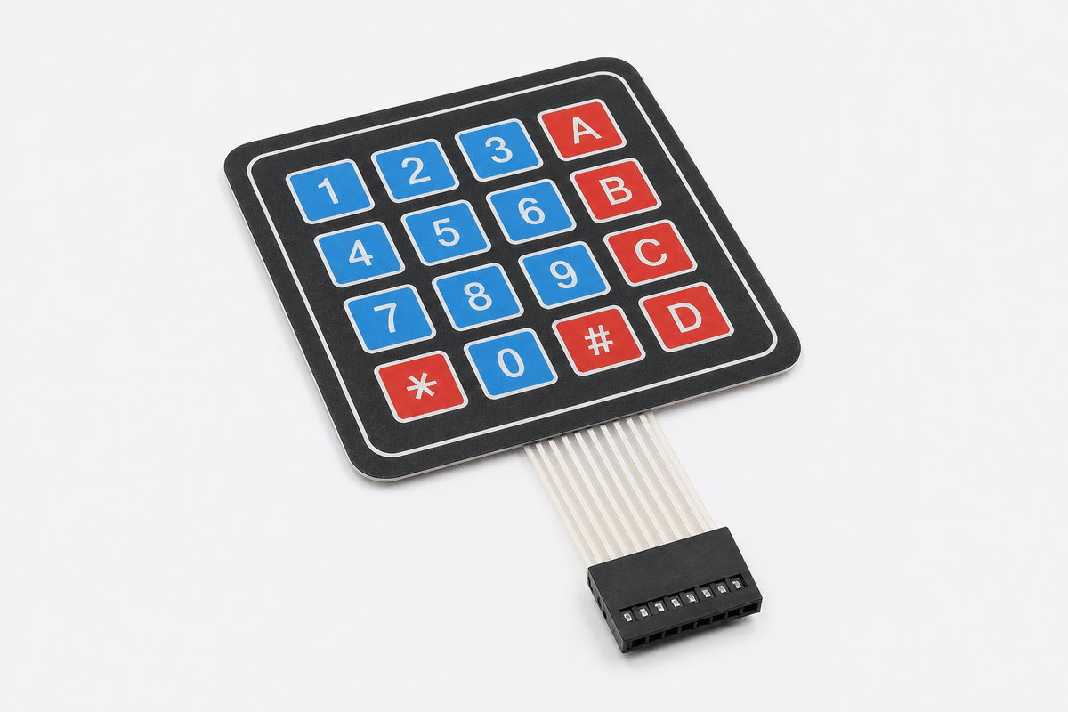
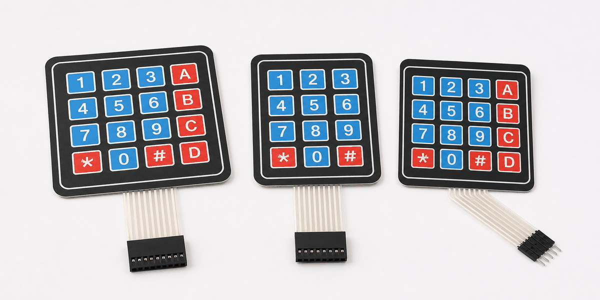
Before we jump into the details, it helps to look at the real module first so the button layout and ribbon connector are easier to understand.
Description
The membrane keypad is a matrix input device. Instead of giving every key its own wire, the keys are arranged in rows and columns so the Arduino can scan the matrix and detect which key is pressed.
That design saves pins and makes it possible to fit many buttons into a small connector. It is why membrane keypads are common in security systems, calculators, door locks, vending machines, and menu-driven projects.
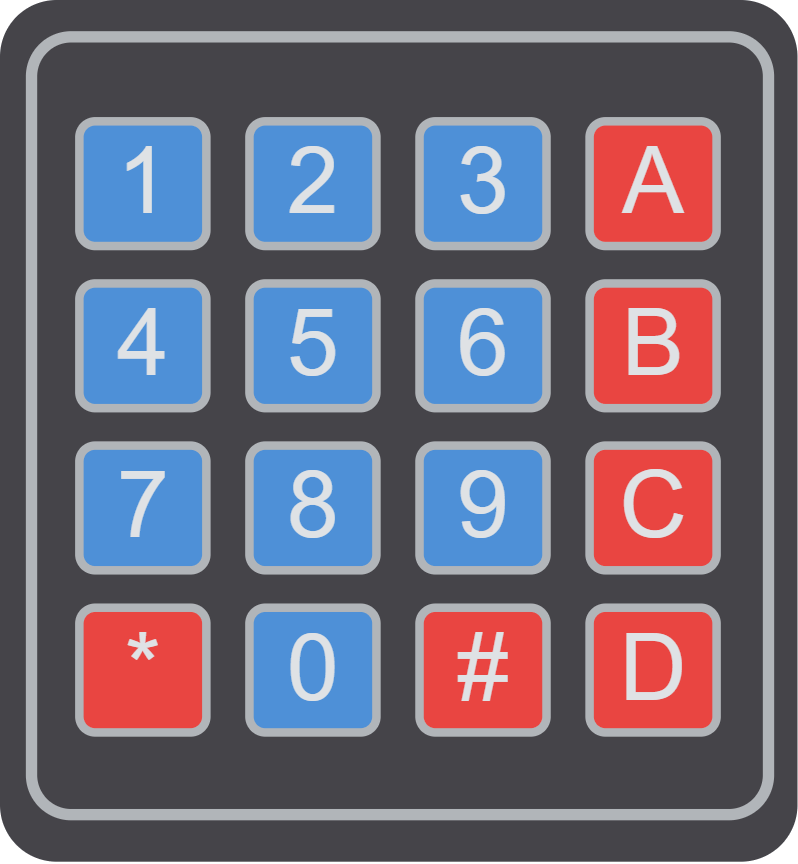
In the simulator, the keypad behaves like a 4x4 matrix, which means the Arduino can read numbers and symbols by scanning the row and column lines together.
Some keypad families also come in smaller or larger layouts, so the physical shape can vary even when the basic scanning idea stays the same. That is why it helps to compare the module with a version image before you start wiring or writing the key map.
Features
Here are the main things to know about the Membrane Keypad:
| Feature | What it means |
|---|---|
| Matrix layout | Uses rows and columns instead of one wire per key. |
| Many inputs | Lets a small connector represent a lot of keys. |
| Library support | Works well with the Arduino Keypad library. |
| Numeric input | Great for PIN entry, menu selection, and command input. |
| Pin efficient | Saves microcontroller pins compared with separate buttons. |
The important part is that the Arduino can find a pressed key by checking the row and column intersection, not by reading a single analog value.
How Does It Work?
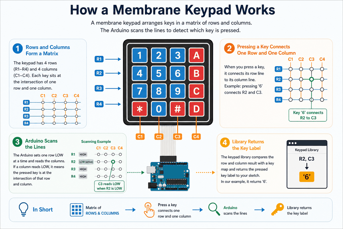
Inside the keypad, every key connects one row line to one column line when pressed. The Arduino scans the rows and columns, looking for a closed path that tells it which button is down.
That is why keypad code usually uses a library. The library handles the scanning logic and gives the sketch a character like 1, 2, A, or # when a key is pressed.
This makes the keypad feel very different from a simple button. It gives you many inputs through a compact set of wires, which is perfect for user entry and small interface projects.
Matrix Scan
The Arduino drives one line at a time and checks which other line becomes active. That scan pattern is what reveals the pressed key.
Library Flow
The library maps the scanned key position to a label in the keys array. That is the value your sketch receives when the user presses a button.
Arduino With Membrane Keypad

This circuit preview shows the membrane keypad connected to an Arduino Uno so you can see the matrix layout before looking at the sketch. Each row and column wire has a specific job, and the scanning logic depends on that order staying consistent.
About Library Keypad
The Keypad library takes care of the scanning work so you do not have to write the matrix logic by hand. It watches the rows and columns, finds the pressed key, and returns a clean character that your sketch can use right away.
That matters because keypad input is not just a simple on or off signal. One press has to be matched against the row and column layout, and the library keeps that process predictable. If the wiring and the key map match, the code stays short and the keypad feels easy to use.
This is the part that makes the article practical. Instead of spending time on low-level scanning code, you can focus on what happens after a key is pressed, like PIN entry, menu selection, or a simple command flow.
Type 4x4 And 4x3 Keypad
Membrane keypads usually come in two common layouts: 4x4 and 4x3. A 4x4 keypad gives you sixteen keys, including letters like A, B, C, and D. A 4x3 keypad gives you twelve keys, which is enough for numbers and a few symbols but leaves out the extra letter column.
The difference is useful in real projects. If you only need a PIN pad or a simple menu, a 4x3 keypad is often enough. If you want more commands or a fuller control panel, the 4x4 layout gives you a little more space to work with without changing the basic scanning idea.
Both types still use rows and columns, so the code pattern stays similar. The main change is the number of columns and the character map you assign in the sketch.
4x4 Code Example
This version matches the full 4x4 keypad layout with four rows and four columns. Use it when you want the letter keys as well as the numbers.
4x3 Code Example
This version matches the smaller 4x3 keypad layout. Use it when you only need numbers and the standard symbol keys.
Pin Connection
The pin connection map below shows the 4x4 matrix layout clearly. Rows and columns work together, and a pressed key only becomes readable when both sides are wired in the right order.
First row line used during matrix scanning.
Second row line used during matrix scanning.
Third row line used during matrix scanning.
Fourth row line used during matrix scanning.
First column line that completes the pressed key path.
Second column line that completes the pressed key path.
Third column line that completes the pressed key path.
Fourth column line that completes the pressed key path.
Once the wiring matches the key map in code, the keypad feels reliable instead of confusing. If a key prints the wrong character, the usual cause is a row or column order that does not match the sketch.
Arduino Code
This example uses the Keypad library to read a pressed key and print it to Serial Monitor. It is a clean starting point for PIN entry or menu selection projects.
Once that works, you can connect the keypad to a password check, a menu, or any other input flow that needs several buttons in a small space.
How The Code Works, Part By Part
Let's break the sketch into smaller pieces so the flow is easier to understand and easier to modify later.
Array Setup
The code begins by defining the keypad size and the character layout. That tells the library which value belongs to each row and column intersection.
Pin Setup
The row pins and column pins are listed next. These are the Arduino pins used to scan the keypad matrix.
Library Object
The keypad object connects the layout to the physical pins. This is the part that lets the library translate a pressed key into a readable character.
Read Key
The loop checks whether a key has been pressed. If so, the sketch prints it to Serial Monitor so you can see the input right away.
Wrapping Up
The membrane keypad is a very useful input part when you need many buttons in a compact layout. It gives you a lot of control without turning the wiring into a mess, which is one reason it shows up so often in passcode systems and menu-driven projects.
Once you understand matrix scanning, the row and column pins, and the Keypad library, the part becomes much easier to trust. If the printed characters do not match the physical buttons, the fix is usually in the row or column order rather than in the library itself. That is the kind of detail that matters in real use, because the keypad can feel broken when it is only wired in the wrong order.
From here, a good next step is to turn this keypad into a simple PIN lock or a menu selector with a few choices. That keeps the project practical and gives the matrix scan a job that feels natural instead of artificial.