This article is a guide about the RGB LED. We will explain how it works, show how the color channels are wired, and walk through an Arduino example you can use in your own projects.
RGB LEDs are useful when a project needs colorful feedback instead of just a single on or off light.
Description
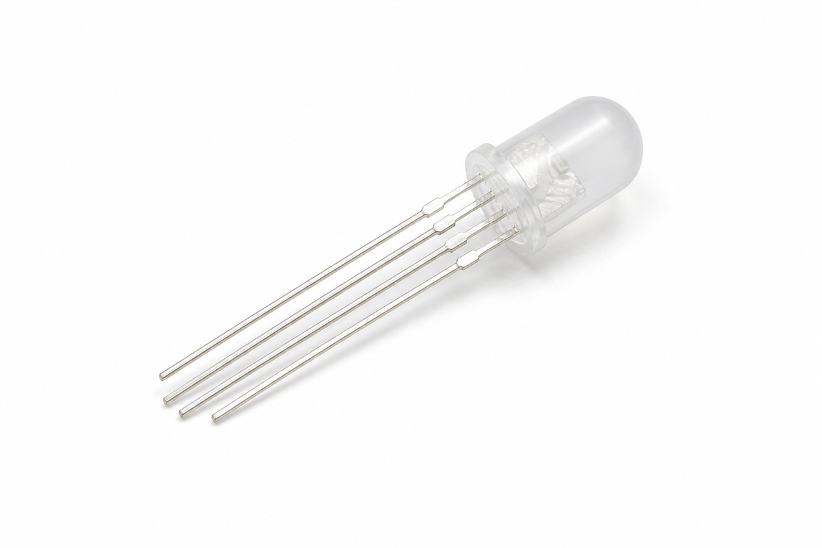
An RGB LED contains three LEDs inside one package: red, green, and blue. By changing the brightness of each channel, Arduino can mix those three colors and create many different shades.
That is why RGB LEDs are popular in mood lights, indicators, simple visual effects, and beginner projects that need a small but flexible display of color. Instead of using several separate LEDs, one package can do the job of many colors at once.
Most RGB LEDs also have one common pin. Depending on the part type, that common pin can be anode or cathode, so the wiring and logic can change a little. Once you understand that detail, the rest of the project becomes easy to follow.
Features
Here are the main things to know about the RGB LED:
| Feature | What it means |
|---|---|
| Three color channels | Red, green, and blue can be controlled separately. |
| Color mixing | Different brightness values create different colors. |
| PWM friendly | Works well with analogWrite() on PWM pins. |
| Common pin | Usually has one shared pin for the LED package. |
| Visual feedback | Great for status lights, effects, and alerts. |
| Beginner friendly | Easy to test and easy to see on the canvas. |
The key idea is simple: the Arduino changes the brightness of each channel, and the eye sees the mixed result as a new color.
How Does It Work?
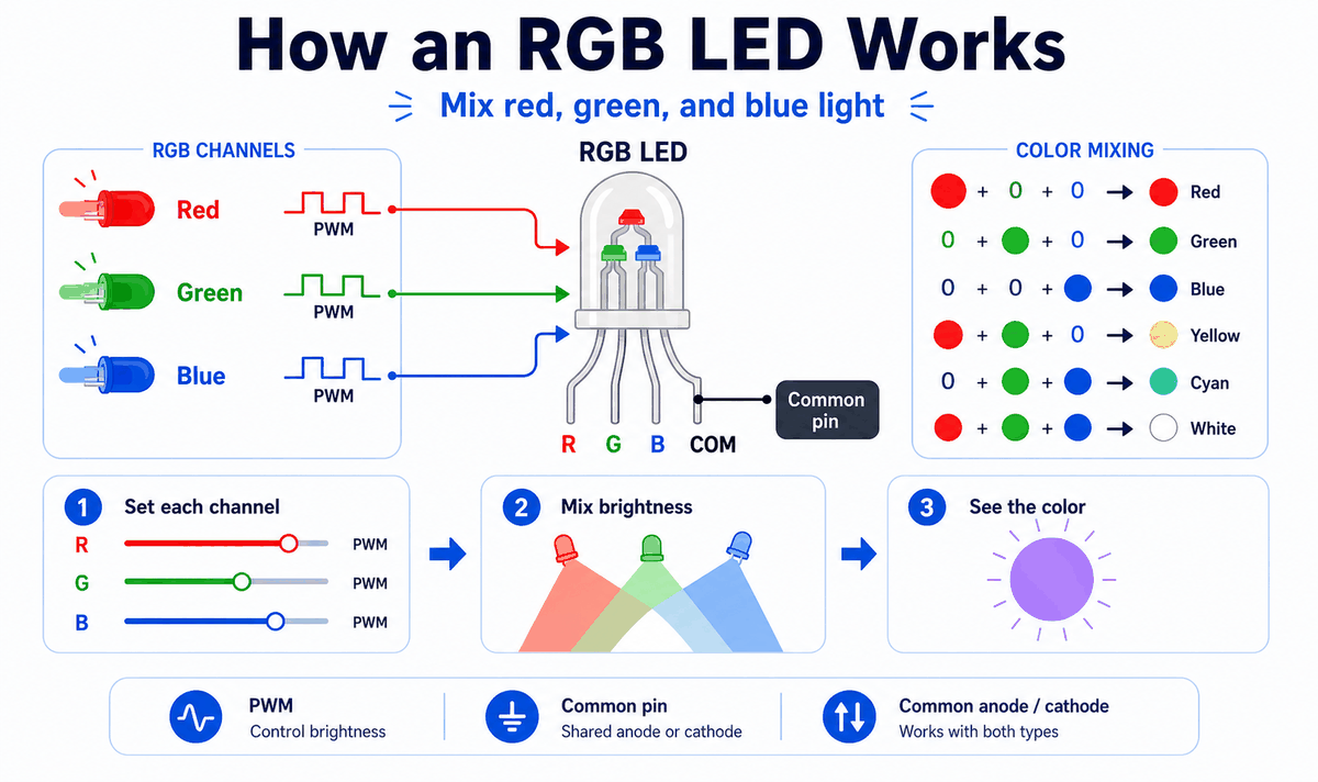
An RGB LED works by combining three light sources into one visible output. The Arduino uses PWM to control how bright each channel appears, then the eye blends the result into a single color.
If one channel is bright and the others are off, you see a pure color. If two channels are on together, you get a mixed color like yellow or cyan. If all three are bright, the LED can look white or near white depending on the part and brightness levels.
Red, Green, And Blue Channels
Each channel behaves like a small LED on its own. Red gives warm tones, green gives a middle tone, and blue gives cool tones. The more brightness you send to one channel, the stronger that color becomes in the final mix.
Common Pin
The common pin is the shared connection for the whole package. Some RGB LEDs are common anode and others are common cathode, so you should always check the part type before wiring the circuit or copying the logic.
That detail matters because common anode and common cathode use opposite control logic. If the LED behaves inverted, the common pin type is usually the first thing to check.
Color Mixing
RGB color mixing is simply brightness control applied to three channels at once. By changing the red, green, and blue values together, you can create a wide range of colors without changing the hardware.
Arduino With RGB LED
This setup shows how to use an RGB LED with Arduino Uno and PWM pins. The key idea is simple: the Arduino controls three color channels, and the common pin tells the LED whether to use common anode or common cathode logic.

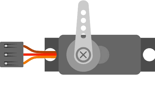
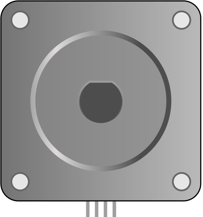
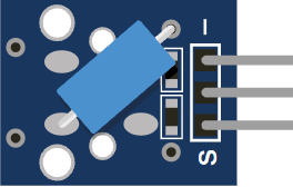
RGB LED Pinout
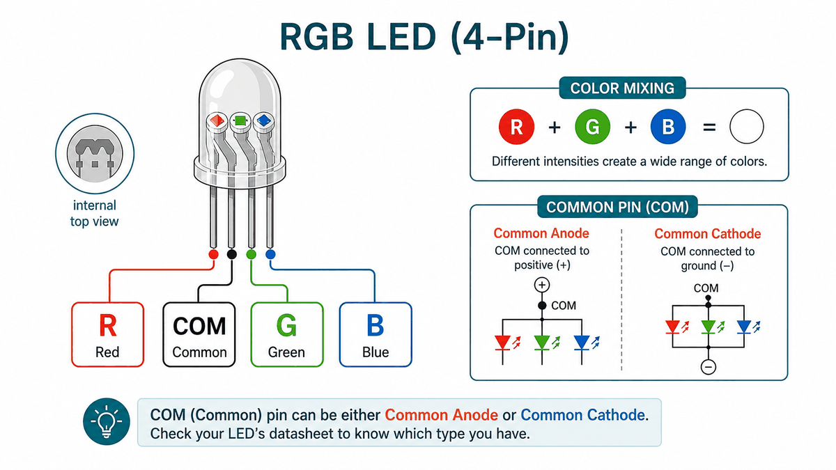
The RGB LED has four pins in this module: one shared common pin and three color pins. The common pin can go to 5V or GND depending on the LED type, while the color pins are the lines the Arduino uses to mix the final color.
If the colors look inverted, the common pin type is usually the first thing to check. That is the small detail that decides whether the LED behaves as common anode or common cathode.
| Pin | What it does | Arduino note |
|---|---|---|
R | Red channel | Often wired to a PWM pin like D9. |
G | Green channel | Often wired to a PWM pin like D10. |
B | Blue channel | Often wired to a PWM pin like D11. |
COM | Shared common pin | Connect to 5V for common anode or GND for common cathode. |
The reason this matters is simple: the RGB LED does not mix color by itself. The Arduino sends three separate brightness levels, and the common pin decides which control logic the part expects.
Once that pinout is clear, the rest of the wiring becomes straightforward. You only need to remember which wire controls each color and whether the common pin should go high or low.
Connections
The RGB LED module in this simulator exposes four pins: R, COM, G, and B. The three color pins connect to PWM-capable Arduino pins, and the common pin connects according to whether the part is anode or cathode.
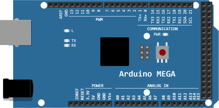
For an Arduino Uno, PWM pins such as 9, 10, and 11 are a common choice because they let you change brightness smoothly with analogWrite().
Controls the red channel with PWM.
Controls the green channel with PWM.
Controls the blue channel with PWM.
Connects to 5V for common anode or GND for common cathode.
If your LED is common anode, the common pin goes to 5V and the color pins are driven with inverted PWM values. If it is common cathode, the common pin goes to GND and normal PWM values are used.
Code
This example cycles through a few common colors. It uses PWM so the LED can mix different brightness levels instead of just turning fully on or fully off.
The helper function makes the code easier to read and also handles common anode inversion in one place. That keeps the loop simple and makes it easier to add more colors later.
How The Code Works, Part By Part
Let's break the sketch into smaller pieces so the color logic is easier to understand and easier to modify later.
Pin Setup
The sketch starts by storing the three color pins in variables. Then it sets each one as an output because the Arduino will drive the LED channels directly.
Color Helper
The helper function receives brightness values for red, green, and blue. If the LED is common anode, the code flips the values before sending them to analogWrite().
Color Steps
Each call to setColor() sends a different brightness combination to the LED. That is what creates red, green, blue, yellow, white, and off states in the loop.
Repeat
The loop keeps the color pattern running so the RGB LED continues cycling through colors as long as the sketch is active.
Wrapping Up
The RGB LED is a great component when you want color feedback instead of a single on or off indicator.
Once you understand the common pin, PWM control, and color mixing, you can use this part in warning lights, mood indicators, or any project that needs a small but expressive visual signal.