This article is a guide about the Tilt Switch. We will look at how the contact moves, how the Arduino reads the state, and how to wire it in a simple digital circuit.
The Tilt Switch is useful when a project needs to know whether something is upright, upside down, or moved to a different angle. It gives you a quick yes-or-no answer from a physical tilt instead of a continuous motion reading.
Description
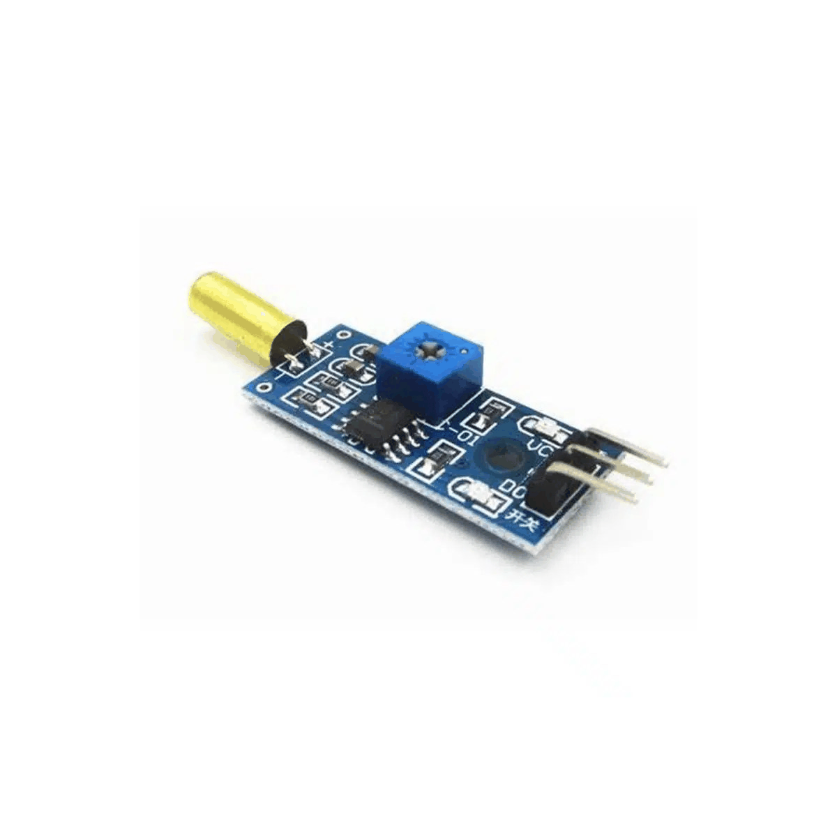
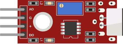
A tilt switch is a simple mechanical sensor that opens or closes depending on its angle. Inside the module, a small metal contact moves when the sensor is tilted, which changes the electrical state seen by the Arduino.
That makes it a handy part for orientation checks, alarm triggers, toy projects, and beginner experiments where you want the board to react to movement without needing a complex motion sensor. It is closer to a switch than a true motion sensor, which is why the reading stays easy to work with.
Features
Here are the main things to know about the Tilt Switch:
| Feature | What it means |
|---|---|
| Mechanical action | The contact changes state when the module tilts. |
| Digital output | The Arduino reads a simple HIGH or LOW signal. |
| Easy wiring | Usually only needs VCC, GND, and OUT. |
| Orientation use | Great for upright or moved detection. |
| Contact bounce | The reading can flicker for a moment when the sensor settles. |
| Small footprint | Fits neatly into compact alarm and toy projects. |
The useful part is that the module behaves like a tiny switch that changes when the angle changes. That makes it easy to use for orientation alerts and simple motion checks, especially when you only need a clean digital state instead of a more complex motion value.
How Does It Work?
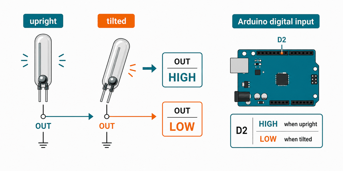
When the module is in one position, the internal metal contact makes or breaks the connection. When you tilt the sensor, the contact moves and the output state changes. The Arduino can then treat that change as a digital input event.
In practice, the reading can bounce for a moment while the contact settles. That is normal for a mechanical switch, so a short delay or simple debounce logic helps if the signal changes too fast.
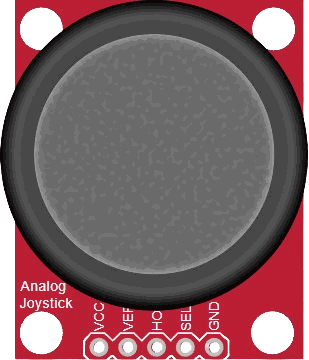
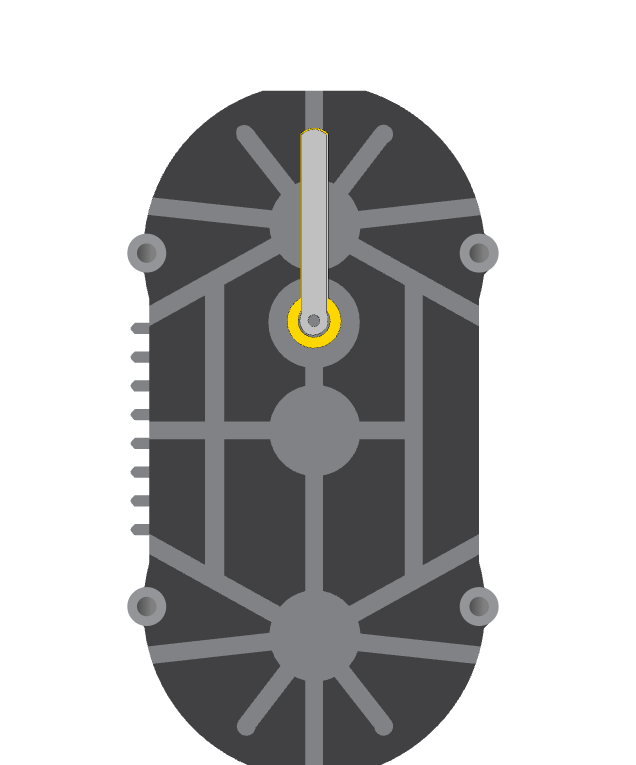
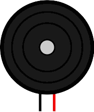
Testing a Ball Tilt Sensor
This is the simple version of a tilt sensor most beginners meet first: a small ball rolls inside the tube and touches the contact when the module leans. When the sensor stands one way, the ball completes the circuit. When it tilts the other way, the ball rolls away and the circuit opens again.
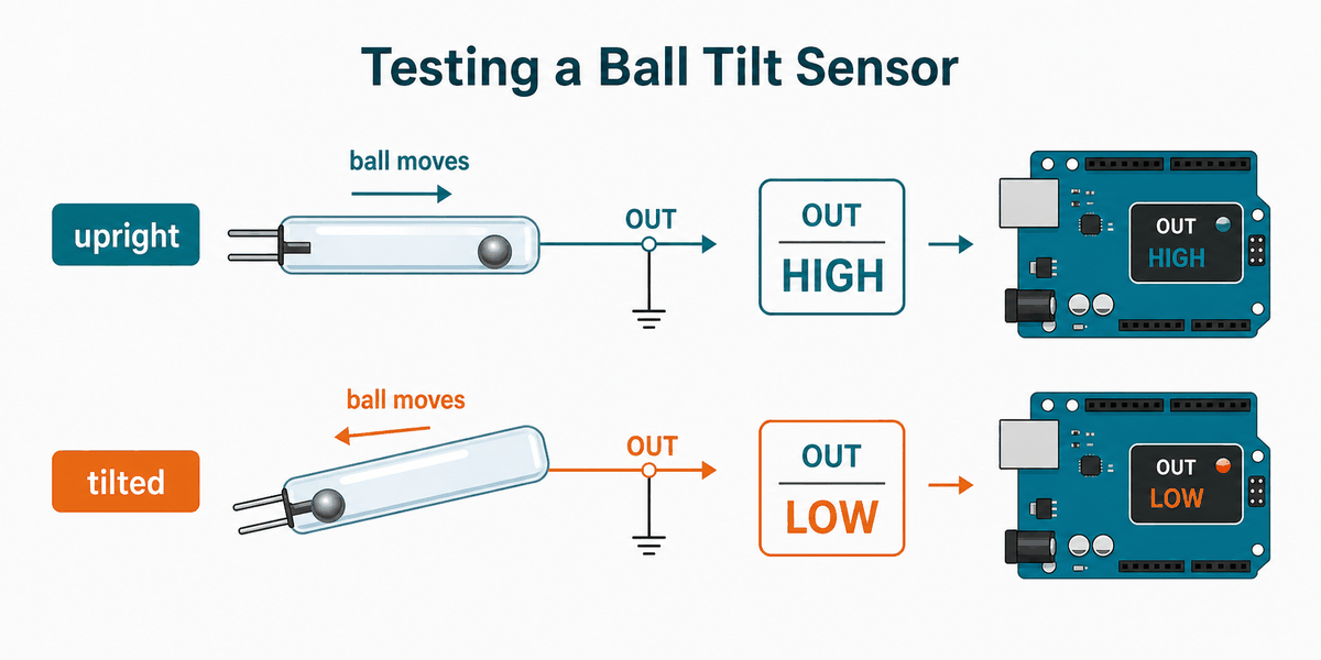
That rolling-ball behavior is why the reading feels instant but not perfectly stable. If the sensor is sitting near the edge of its angle range, the ball can rattle a little before it settles, so a tiny debounce delay is often enough to clean up the signal.
In the simulator, you can flip the switch state and watch the OUT pin change right away. That makes it easy to understand how a tilt-based on/off sensor behaves before using it in a real project.
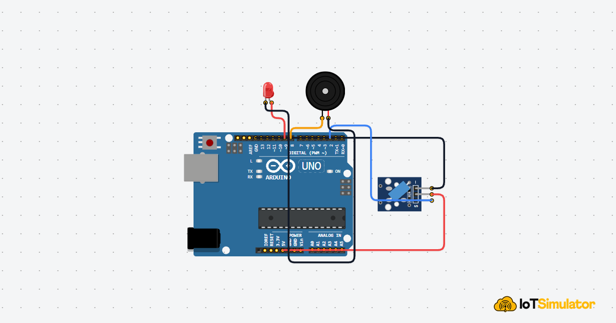
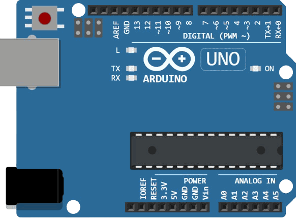
Arduino With Tilt Switch
This circuit preview shows the tilt switch connected to Arduino Uno. It is a simple digital input setup because the sensor only needs to tell the sketch whether the module is tilted or not.

Pin Connection
The pin map below matches the circuit preview. Power keeps the sensor running, ground completes the circuit, and OUT carries the tilt state back to the Arduino.
Supplies power to the sensor module.
Shares the ground reference with the Arduino.
Carries the tilt state into the sketch.
With this wiring, you usually do not need analog pins or complex timing code. The sensor is best read as a straight digital input, which keeps the sketch easy to follow.
Code
This example turns on the built-in LED when the tilt switch is active and prints the state to Serial Monitor. It is a good first test because the result is easy to see on the board and in the serial output.
The sketch is intentionally simple so you can see the whole flow at once. If you later want to trigger a buzzer or relay, you can replace the LED output with any action you want. The important part is that the tilt event becomes a normal digital decision in code.
How The Code Works, Part By Part
Let's break the sketch into smaller pieces so the flow is easier to understand and easier to modify later.
Setup
The setup block prepares the tilt pin as an input with a pull-up resistor and turns the LED pin into an output. This gives the Arduino a stable signal to read.
Read The Switch
This part checks whether the tilt switch has changed state. Because the input is pull-up based, a tilted or closed switch reads as LOW.
React To Tilt
Here the sketch decides what to do when the switch is active. In this example, the LED turns on and the serial monitor shows a message.
Repeat
The loop keeps checking the sensor so the Arduino can react every time the module changes angle. That is what makes the tilt switch useful for orientation-triggered actions.
Wrapping Up
The Tilt Switch is a very simple but useful input part when you want the Arduino to know if something has moved or tilted. It is easy to wire and easy to understand, which makes it a nice sensor to learn before moving on to more complex motion parts.
Once you understand the digital state change, you can use it for alarms, orientation checks, and other small interactive projects. The real value is that you get a clear yes or no answer from a physical movement, without needing much code. If the signal flickers, that usually means the contact is settling and needs a little debounce handling.