This article is a guide about the Analog Joystick. We will explain how it works, show its wiring, and walk through an Arduino example you can use in your own projects.
Joysticks are useful when a project needs human control instead of a fixed sensor reading. They are often used in game controllers, robot direction control, menu navigation, and small interface panels where the user needs to move something up, down, left, right, or press a button.
Before looking at the pin layout, it helps to know what the module is actually doing inside the housing. That will make the next sections easier to follow.
Description
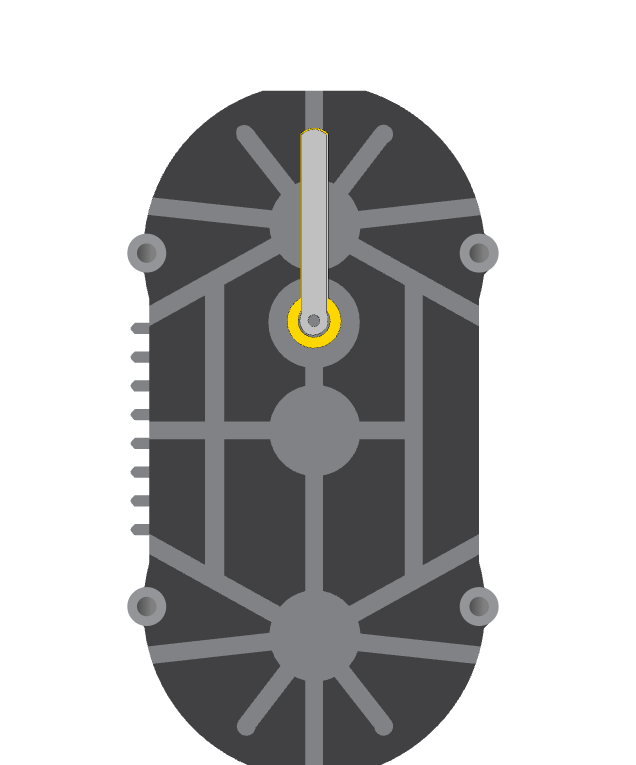
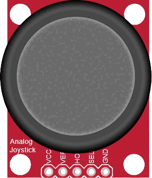
An analog joystick looks like a small game controller stick, but inside it is really a pair of potentiometers and a pushbutton. When you move the stick, the module changes the voltage on the X and Y output lines. When you press the stick downward, the center switch closes and acts like a button.
That combination makes it very handy for interactive projects because one part can give both movement and click input. The Arduino can read the analog values to know where the stick is pointing, then read the switch to know when the user pressed it.
In simple projects, the joystick is often used to control direction, choose menu items, or move a cursor. In more advanced projects, the same module can drive motors, control a camera pan, or navigate a small UI on a display.
Features
Here are the main things to know about an analog joystick:
| Feature | What it means |
|---|---|
| Two analog axes | Gives separate X and Y movement values so the Arduino can detect direction. |
| Center voltage | The idle position sits near VCC/2, which is why the readings usually settle in the middle. |
| Axis polarity | HORZ and VERT move in opposite numeric directions depending on which side you push. |
| Pushbutton | The stick can also be pressed like a switch through the SEL pin. |
| Button bounce | The press signal can bounce, so pull-up logic and a small delay help keep it stable. |
| Dead-zone friendly | The center can drift slightly, so projects usually ignore a small middle range. |
| Interactive control | Great for menus, robot steering, cursor movement, and game input. |
The module is simple, but it gives a project a very natural user feel. A single thumb can move the stick, and the board can immediately react to direction, speed, and the press state. That is what makes it feel more like a real controller than a plain sensor.
One helpful detail is that the joystick does not just report "left" or "right" in a binary way. It gives you a moving analog value, so you can decide how far the stick was pushed and use that to control speed, menu scrolling, or cursor movement more smoothly.
How Does It Work?
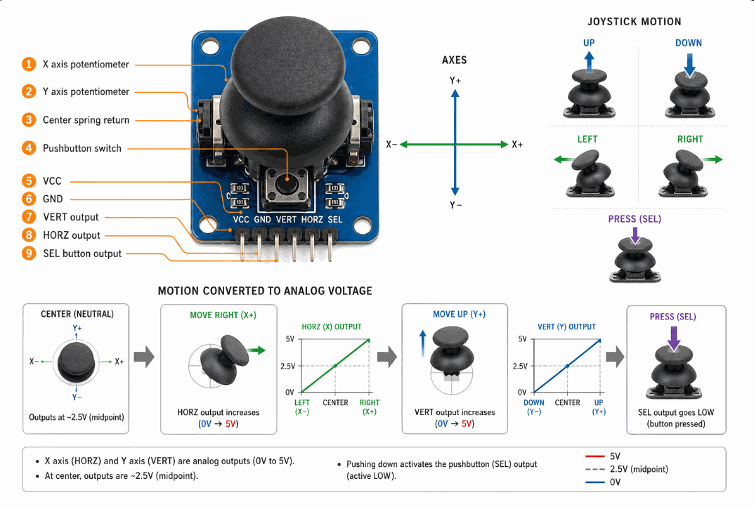
The joystick works by turning movement into voltage changes. When the stick moves left, right, up, or down, the internal resistive sensors change their output values. The Arduino reads those changes with analogRead() and gets a number that tells it how far the stick moved from the center.
At the center position, the joystick usually sits near the middle of the analog range. On an Arduino Uno, that reading is often around 512 because the board uses a 10-bit analog converter. Wokwi models the idle position as VCC/2, which is a helpful mental model when you are trying to understand why the stick settles in the middle.
The center button works separately from the analog axes. It does not give a number like the X and Y lines do. Instead, it behaves like a switch that tells the Arduino whether the stick is pressed down or not.
Center Position
When you release the joystick, it springs back toward the middle. That resting point is important because many projects treat it as the neutral position. If the stick is not being pushed, the readings should stay close to center.
In practice, the center value can drift a little, so many sketches use a small dead zone around the middle. That keeps tiny hand motion or sensor noise from making the project move when the stick looks like it is still.
X And Y Axes
The X axis changes when you move the stick left or right, and the Y axis changes when you move it up or down. In the Wokwi analog joystick reference, the horizontal output increases toward the left side and the vertical output increases toward the top, so direction handling can feel inverted if you expect the opposite.
That is why joysticks are a good choice for motion controls and menus. The code can compare both values at the same time and decide whether the user wants to move up, down, left, right, diagonal, or stay in the center.
Pushbutton
Pressing the joystick downward closes the center switch. In Arduino code, this is usually read as a digital input with a pull-up resistor, so the value goes LOW when the button is pressed.
That extra button makes the module more flexible than a plain two-axis sensor. You can use the axes for movement and the switch for select, confirm, or action input in the same project.
Direction Mapping
Raw values are useful for debugging, but real projects often map the readings into a smaller range. That makes it easier to decide whether the stick is being pushed a little or a lot. The map() function is often used to convert the analog values into percentages or game-control values.
For example, you might convert the horizontal axis into -100 to 100 so the joystick becomes easier to use for robot steering, cursor movement, or speed control.
Dead Zone
A dead zone is a small center area where the sketch treats the joystick as neutral. This is important because the stick may not return to exactly the same number every time, and tiny drift can make the project feel noisy.
With a dead zone, values near the middle are ignored. That makes the stick much easier to use for menus and movement controls because the project only reacts when the user really pushes it away from center.
Explanation Per Part of Analog Joystick
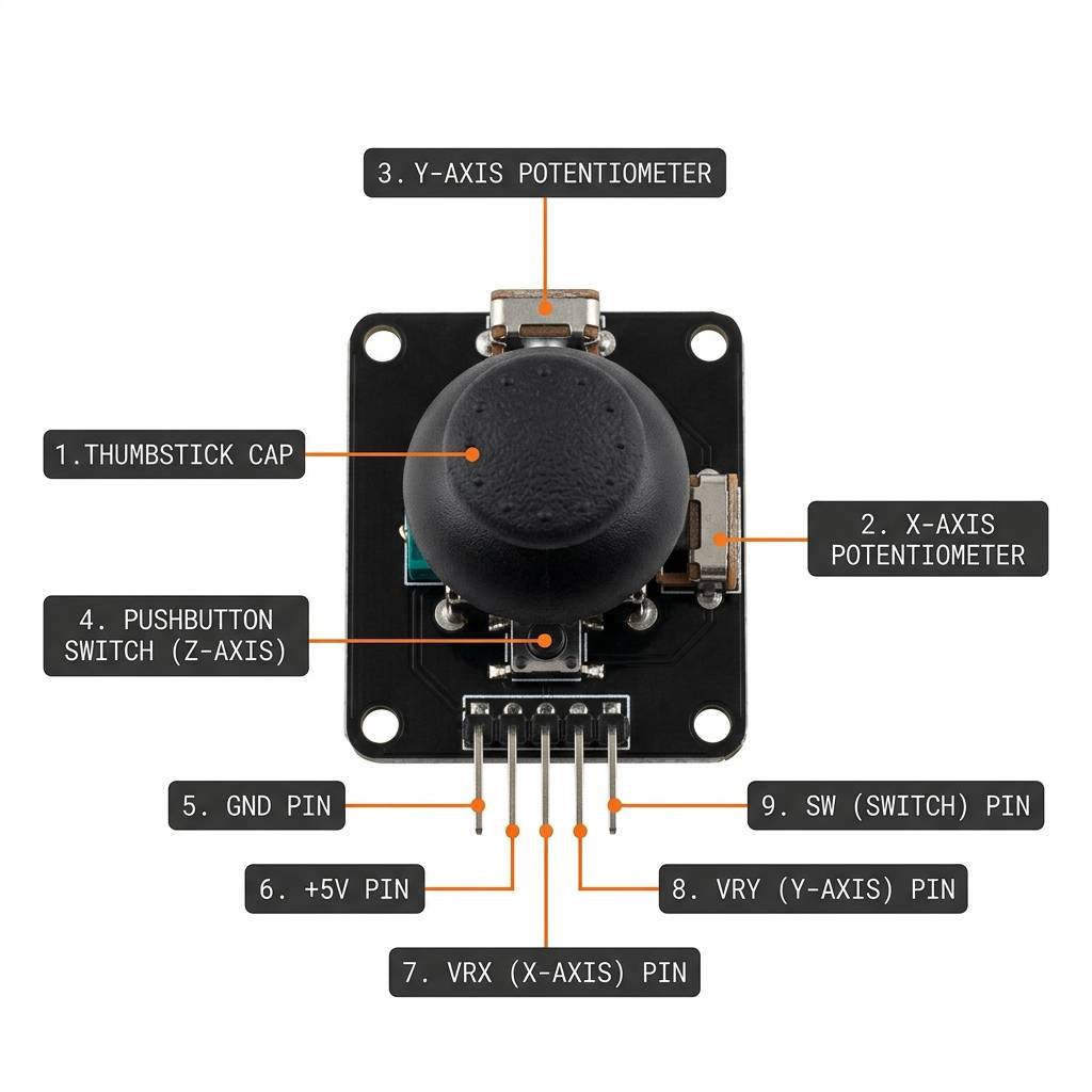
The joystick module is built from two analog axes and one pushbutton. Each part has a specific job, and understanding those parts makes the module easier to use in any project.
| Joystick Pin | Part Role | Signal Type |
|---|---|---|
VCC | Powers the module | Power |
GND | Shared electrical reference | Ground |
VERT | Vertical movement output | Analog |
HORZ | Horizontal movement output | Analog |
SEL | Center press switch | Digital |
For a beginner build, this is a very friendly component to understand. Once you know what each part does, the wiring and sketch logic become much easier to follow.
Arduino With Analog Joystick
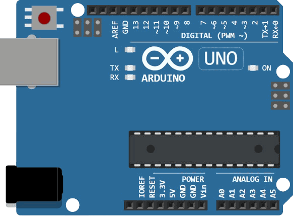
This wiring example connects the joystick to an Arduino Uno in the most common way: power and ground go to the board first, the vertical and horizontal outputs go to analog inputs, and the press switch goes to a digital pin with pull-up logic.
The layout below is easy to remember. VCC powers the module, GND completes the circuit, VERT maps to A0 for vertical movement, HORZ maps to A1 for horizontal movement, and SEL maps to D2 for the click action.

This circuit shows the joystick connected to an Arduino Uno in the same way many beginner projects are wired. The Arduino reads the two axes as analog signals and the press switch as a digital input, so you can use the same wiring for menus, robot control, or cursor movement.
Code
This sketch reads the X axis, Y axis, and button state, then prints them to Serial Monitor. That makes it easy to test the module before you connect it to a motor, a menu, or a game control. The example also adds a small dead zone so the center position stays calm instead of jumping around.
The sketch is intentionally small so you can see the raw input values clearly. Once you understand the readings, you can convert them into direction commands, menu movement, or movement speed in your own project.
How The Code Works, Part By Part
Let's break the sketch into smaller pieces so each part is easier to understand.
Pin Setup
First, the sketch stores the joystick pins in variables. That makes the code easier to read and easier to change later if you want to move the module to different pins.
Reading The Axes
analogRead() reads the X and Y voltages and returns a number from 0 to 1023 on the Arduino Uno. The center position is usually near the middle of that range, while movement in either direction pushes the values up or down.
Reading The Button
The button uses INPUT_PULLUP, so the input stays HIGH when it is not pressed and becomes LOW when the stick is pushed down. That is why the code checks for LOW to decide whether the button is pressed.
Mapping The Range
After reading the raw values, many projects map them into a smaller range. That gives your sketch a cleaner control signal for speed, position, or menu movement.
Printing The Values
Finally, the sketch sends the readings to Serial Monitor. That gives you a quick way to see whether the joystick is moving correctly and whether the button press is working.
Dead Zone And Calibration
Real joysticks do not always return exactly the same center value every time. The springs inside the module, tiny manufacturing differences, and small hand movements can all push the reading a little away from the true middle. A dead zone helps the sketch ignore that small drift so the control feels calm instead of jumpy.
A good dead zone is usually just wide enough to cover the tiny noise near the center, but not so wide that the stick feels lazy. If the dead zone is too small, the cursor or robot may move when you think the joystick is resting. If it is too large, the stick will feel unresponsive until you push it much farther away from the center.
Calibration is the step where you measure the center value from your own module and use that number as the baseline. Different joysticks can sit a little above or below 512, so using your real center reading makes the project feel smoother and more accurate. Many sketches store the center once at startup or use the first few samples to find a stable baseline.
Calibration Step
To calibrate the joystick, read the X and Y pins while the stick is untouched, then save those numbers as the neutral point. After that, compare future readings against the saved values instead of assuming the center is always exactly 512.
That approach is helpful for menu controls, cursor movement, and robot steering because it keeps the control behavior consistent across different joystick modules.
Dead Zone Tuning
Once the center is known, you can define a small range around it and treat that range as neutral. Inside the range, the joystick does nothing. Outside the range, the sketch begins to react and convert movement into direction or speed.
This is the part that turns a raw analog reading into a comfortable user interface. A well-tuned dead zone makes the joystick feel stable, predictable, and much easier to use in a real project.
Wrapping Up
The analog joystick is a simple but powerful input module. It gives you two movement axes and a press button in one part, which makes it very useful for interactive Arduino projects.
Once you understand the analog readings, the center position, and the button logic, you can use the joystick for controls, menus, games, and robot movement with confidence.