This article is a guide about the Arduino Nano. We will explain how it works, show its pinout, and walk through an Arduino example you can use in your own projects.
The Nano is one of the easiest boards to place on a breadboard because of its small size. That makes it a good choice for compact projects, prototype builds, and circuits where you want the same Arduino style programming without taking up much space.
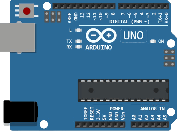
Before jumping into the board details, it helps to look at the Nano itself so the tiny footprint, header layout, and hardware shape are easier to understand.
Description
The Arduino Nano is Arduino's classic breadboard-friendly board with a very small footprint. It uses a Mini-B USB connector, has no dedicated power jack, and is designed for projects that need a compact controller but still want the familiar Arduino workflow.
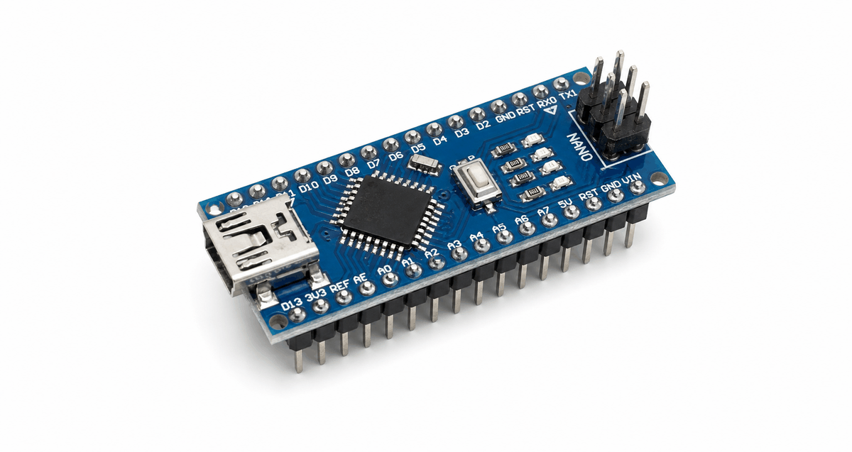
According to Arduino's official documentation, the Nano is the oldest member of the Nano family and is meant for breadboard use. The Nano measures about 45 mm by 18 mm, weighs roughly 7 grams, and uses the ATmega328 microcontroller with a 16 MHz clock.
That mix makes it useful for small robots, sensor circuits, low-profile enclosures, and quick prototypes. It is small, but it still gives you enough flexibility for many practical Arduino projects.
Features
Here are the main things to know about the Arduino Nano:
| Feature | What it means |
|---|---|
| ATmega328 microcontroller | The core chip that runs your sketch. |
| 16 MHz clock | Standard AVR timing for Arduino code. |
| 22 digital I/O pins | Enough room for inputs and outputs in compact builds. |
| 8 analog inputs | Useful for sensors and variable readings. |
| 6 PWM outputs | Good for dimming LEDs and driving simple control signals. |
| Mini-B USB | Easy programming and serial communication. |
| 45 x 18 mm footprint | Small enough to fit neatly into breadboard layouts. |
| No dedicated power jack | Keeps the board compact and breadboard focused. |
The Nano is especially attractive when the project needs to stay small but still connect to several parts. It gives you a familiar Arduino feel without the larger board size of an Uno or Mega.
According to Arduino's official store documentation, the Nano can be powered through Mini-B USB, an unregulated external supply, or a regulated 5V supply, which makes it flexible even though it stays physically small.
Limitations And Tradeoffs
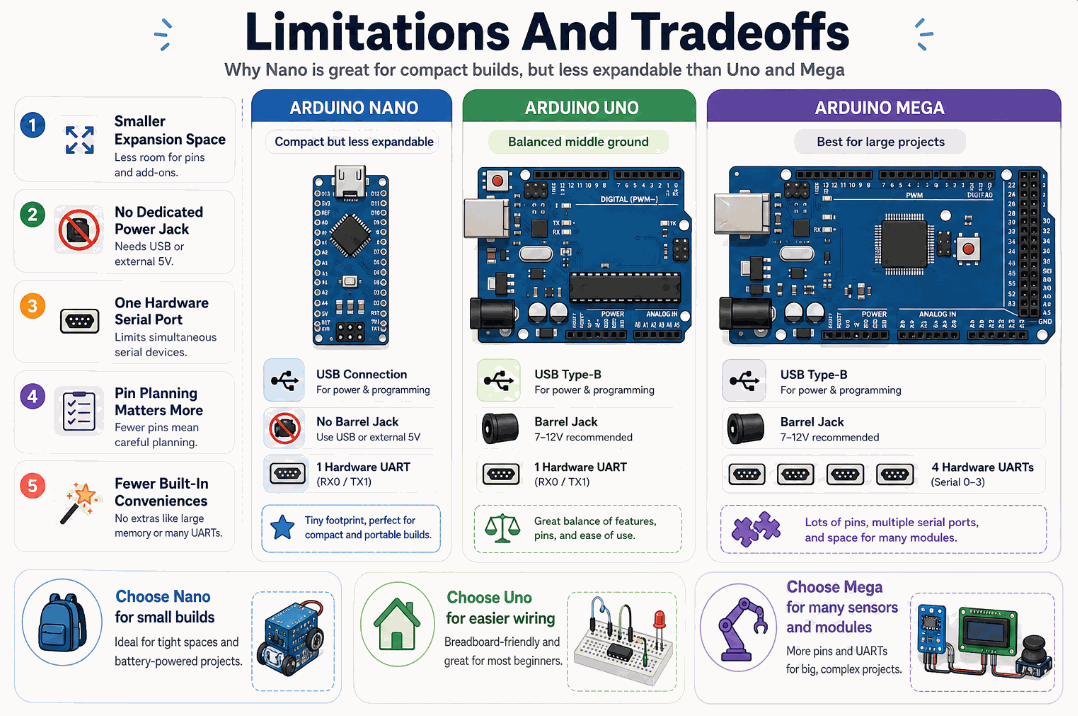
The Nano is one of Arduino's most compact classic boards, but that small size means you give up some comfort compared with the Uno and a lot of expansion room compared with the Mega. This section highlights the main tradeoffs so you can decide when the Nano is the right fit.
Smaller Expansion Space
The Nano is excellent for breadboards and tight enclosures, but it becomes crowded faster than the Uno. The Mega goes even further in the other direction with far more pins and much more room for larger sensor arrays, displays, and control circuits.
No Dedicated Power Jack
The classic Nano relies on Mini-B USB or external power through its header pins instead of a barrel jack. That keeps the board tiny, but it means the power wiring takes a little more planning than it does on the Uno or Mega.
One Hardware Serial Port
The Nano has one main hardware serial connection on D0 and D1. That is enough for many beginner builds, but it is not as flexible as the Mega when you want to talk to multiple serial devices at the same time.
Pin Planning Matters More
Because the board is compact, you need to think about pin usage earlier. A6 and A7 are analog-only, so they cannot be used as normal digital pins. That is a small limitation, but it matters in projects that are already pin-heavy.
Fewer Built-In Conveniences
Compared with the Uno and Mega, the Nano feels more bare-bones. You lose the large board layout, the easy barrel-jack style power setup, and the extra headroom that makes bigger projects easier to wire and debug.
| Tradeoff | Nano | Uno | Mega | What It Means |
|---|---|---|---|---|
| Board size | Smallest | Medium | Largest | Nano wins when space matters most. |
| Power convenience | Mini-B USB, no jack | USB and power jack | USB and power jack | Uno and Mega are easier to power in bench setups. |
| Expansion room | Tight | Balanced | Largest | Mega is better for large multi-module projects. |
| Serial headroom | One main hardware UART | One main hardware UART | Multiple hardware UARTs | Mega is easier when several serial devices are involved. |
| Pin flexibility | A6 and A7 analog-only | All analog pins usable as analog inputs | More total I/O options | Nano needs a little more pin planning. |
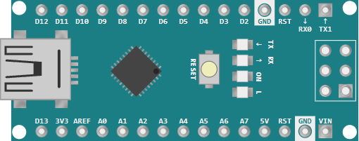
Pinout
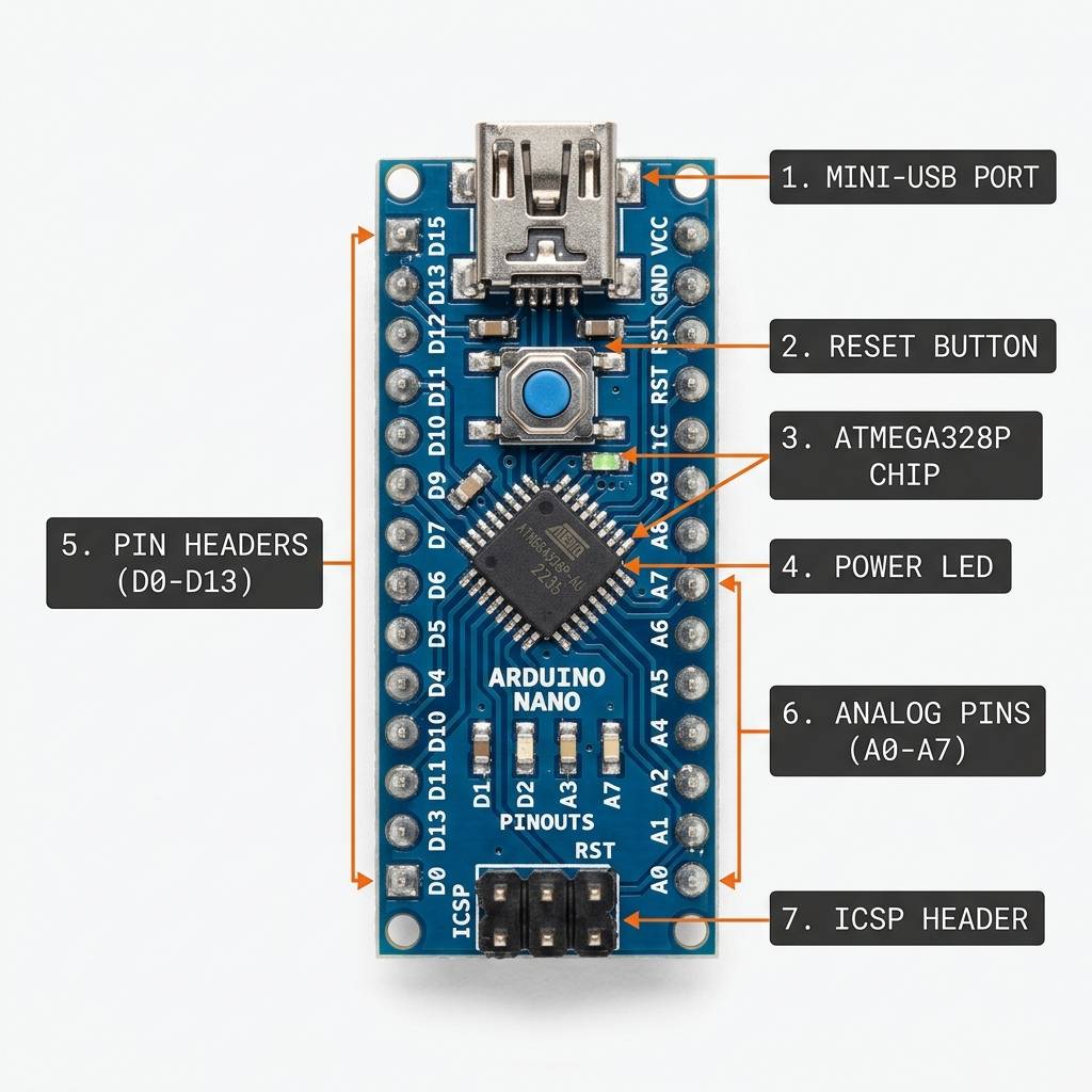
The Nano's pin headers are arranged in two rows. The digital pins and serial pins are on one side, while the analog and power pins are on the other side. That layout is simple to read once you know which row you are looking at.
The official Nano documentation also notes a few special pin roles: D0 and D1 handle serial communication, A4 and A5 are used for I2C, and A6 and A7 are analog-only inputs on the classic Nano.
| Pin Group | What it is used for |
|---|---|
D0-D13 | Digital inputs and outputs, including the hardware serial pins on D0 and D1. |
A0-A5 | Analog inputs for sensors and variable signals, with A4 and A5 also used for I2C. |
A6-A7 | Analog-only inputs on the classic Nano. |
3V3, 5V, VIN, GND | Power and reference connections. |
D10-D13 | Often used with SPI and PWM-capable circuits. |
AREF | Analog reference voltage pin. |
That layout gives the Nano a very usable pin budget for a compact board. It is small, but it still leaves enough room for sensors, outputs, and basic communication buses.
Arduino Nano Wiring Example
This section shows a simple Nano-to-LED circuit, but the same board is also commonly wired to sensors, displays, relays, motors, and communication modules. The Nano is small, so knowing which pins are most useful helps you plan a cleaner build from the start.
Common Pins For Other Components
These are the pins people usually reach for first when they connect the Nano to another component:
| Pin Group | Common Use | Why It Matters |
|---|---|---|
D2-D13 | Buttons, LEDs, buzzers, relays, and simple digital sensors. | These pins are the easiest way to turn something on, off, or read a basic signal. |
D3, D5, D6, D9, D10, D11 | PWM output for LED dimming, motor speed control, and other variable outputs. | These are the pins most often used when a component needs smooth control instead of only HIGH or LOW. |
D0, D1 | Serial modules like Bluetooth, GPS, or USB-to-serial communication. | These pins connect to the Nano's hardware UART, so they are important for communication projects. |
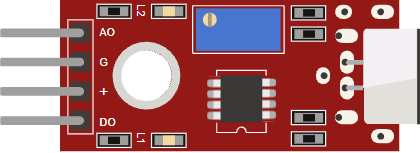
A0-A5 | Analog sensors such as potentiometers, light sensors, gas sensors, and temperature modules. | These pins let the Nano read changing values instead of only digital on/off states. |
A4, A5 | I2C devices like OLED displays, RTC modules, and some sensor boards. | One pair of pins can talk to many I2C modules, which saves space on a compact board. |
A6, A7 | Extra analog inputs on the classic Nano. | These are useful when you need more analog channels, but they are analog only. |
5V, GND, VIN | Power for modules and external supplies. | Every circuit needs a shared ground and the right voltage level to work correctly. |
If you are wiring a first project, start with GND and power, then assign your signal pins based on the component type. Digital parts usually go to D pins, analog sensors usually go to A pins, and communication modules often use D0-D1 or A4-A5.

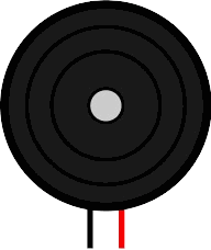
This simple circuit shows the Nano driving an LED through a resistor. It is the same kind of first test many Arduino projects use, and it is a good way to confirm that the board, the sketch, and the wiring are all working together.
From there, the same wiring idea scales up to more useful components: a button on a digital pin, a sensor on an analog pin, an OLED on I2C pins, or a Bluetooth module on the serial pins.
Arduino Nano Wiring Details
For a beginner test, connect the LED anode to pin 13 through a resistor and connect the cathode to ground. That gives you a safe and easy circuit that can blink from the Nano without extra complexity.
When you move on to sensors or displays, the same idea still applies: power, ground, and the signal pin all need to be connected correctly before the code can do anything useful. Most modules follow this same pattern, even if the signal pin changes from digital to analog or I2C.
Code
This example blinks the LED on pin 13 and prints the state to Serial Monitor. It is short enough for beginners, but it still shows the core Nano workflow: set up the pin, write HIGH, write LOW, and repeat.
The sketch is intentionally simple so you can focus on the board behavior instead of on complex logic. Once this works, you can reuse the same Nano with buttons, sensors, displays, or a small motor driver.
How The Code Works, Part By Part
Let's break the sketch into smaller pieces so the flow is easier to follow.
Pin Setup
First, the sketch stores the LED pin number in a variable and sets that pin as an output. That tells the Nano the pin will be used to drive a device instead of reading one.
Turn On
When the pin goes HIGH, the Nano provides voltage to the LED path. If the LED is wired with the correct polarity and a resistor is in series, the LED lights up.
Turn Off
When the pin goes LOW, the voltage difference disappears and the LED turns off. That creates the blinking effect.
Repeat
The loop() function runs continuously, so the on and off pattern keeps repeating until you stop the program or upload new code.
Wrapping Up
The Arduino Nano gives you classic Arduino behavior in a very small package. Once you understand the pin layout and the basic power options, it becomes a very easy board to use in compact projects.
If you want a board that fits neatly on a breadboard but still gives you plenty of familiar Arduino pins, the Nano is one of the best places to start.