This article is a guide about the 7-Segment Display. We will explain how it works, show its pinout, and walk through an Arduino example you can use in your own projects.
A 7-segment display is a great fit when a project only needs digits, a decimal point, or a small numeric readout. That is why you often see it in timers, counters, clocks, meters, and simple status panels.
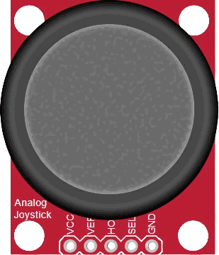
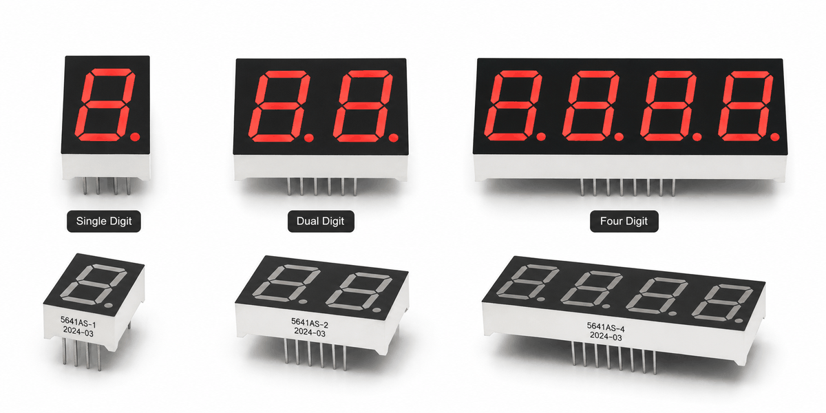
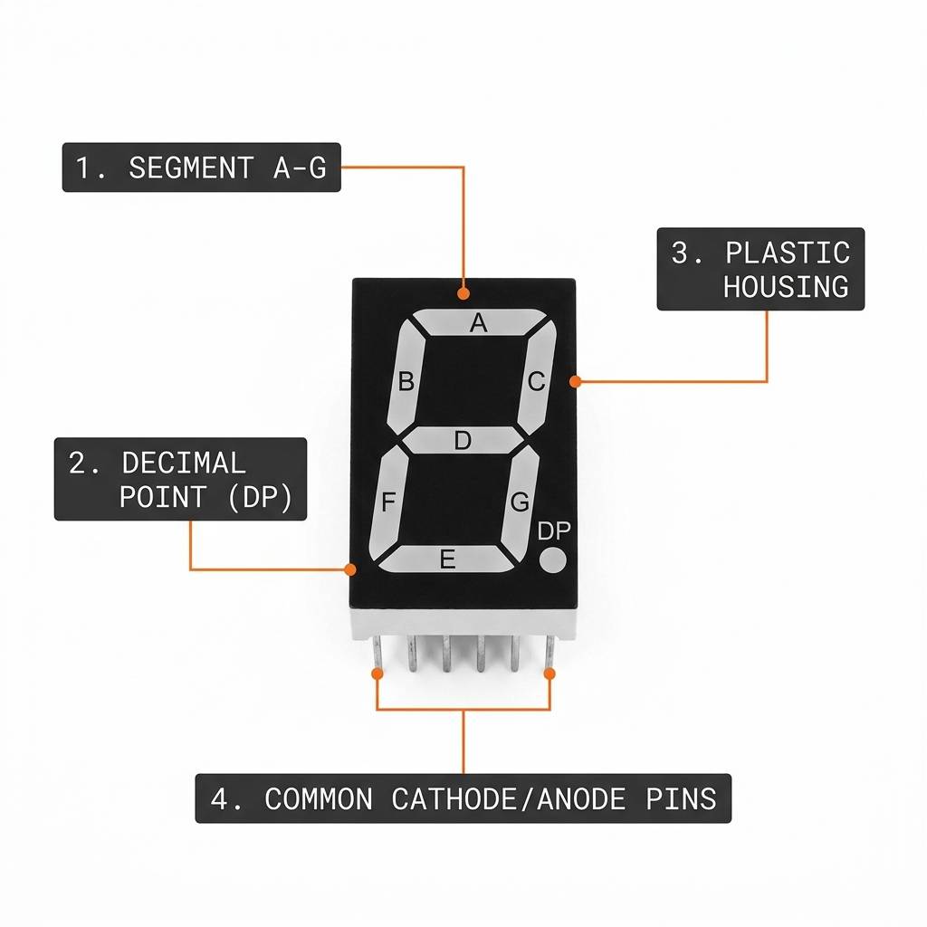
Before we jump into the description, it helps to look at the real module first so the shape, digit layout, and version differences are easier to understand.
Description
A 7-segment display is made from seven tiny LED bars named A through G, plus an optional decimal point. By turning the right segments on or off, the display can form the numbers 0 to 9 and a small set of extra symbols.
These displays come in several physical versions, from single-digit modules to dual-digit and four-digit packages. That is why the same component family can be used for a tiny counter, a timer, or a wider numeric readout.
Most hobby displays come as common cathode or common anode modules. In a common cathode display, the common pin goes to ground and a HIGH signal lights a segment. In a common anode display, the common pin goes to 5V and a LOW signal lights a segment.
That difference matters because the same sketch will work in the opposite way depending on the module type. Once you know which type you have, the display is easy to drive from an Arduino or any other microcontroller.
Features
Here are the main things to know about a 7-segment display:
| Feature | What it means |
|---|---|
| Seven LED segments | Segments a through g combine to form digits and a few symbols. |
| Decimal point | Lets the display show a decimal marker or a simple status dot. |
| Common cathode or anode | Changes whether a HIGH or LOW signal lights the segment. |
| Single, dual, and four-digit packages | Same basic segment idea, but with more digits available in one part. |
| High-luminescence output | Useful when the number needs to stay readable at a glance. |
| Low pin count for single digits | Easy to wire for a small one-digit readout. |
| Current limiting | Each segment is still an LED and needs safe current control. |
| Multiplex-friendly | Multi-digit modules can share segment lines and scan each digit quickly. |
It is not meant for long text, but it is excellent for showing numbers clearly and with very little power. That makes it a classic choice for beginner projects and practical embedded interfaces.
How Does It Work?
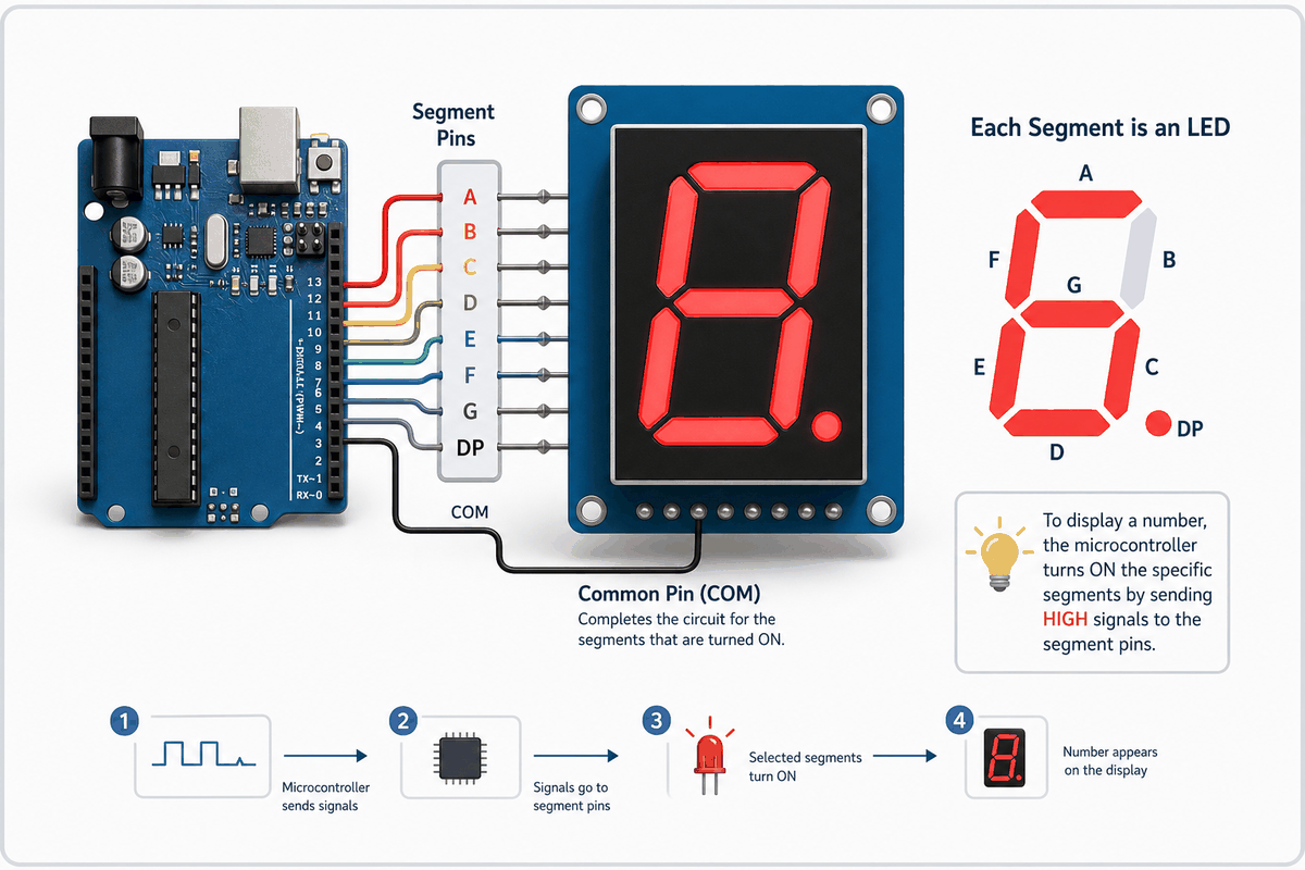
The idea is simple: each segment acts like a small LED. The Arduino sends signals to the segment pins, and the lit segments combine to form a digit that the user can read quickly.
In a common cathode module, all of the segment LEDs share ground. In a common anode module, they share 5V instead. That means the Arduino is not sending a ready-made number to the display. It is lighting specific bars, and those bars together create the digit you see.
The most important idea is the segment map. Each number has its own pattern, so the sketch needs a table or helper function that knows which segments should turn on. Once that mapping is ready, the display can show digits clearly with only a few pins.
That is why the 7-segment display is such a good beginner component. It looks simple from the outside, but it teaches an important idea in electronics: a visible output is often just a set of smaller parts working together in a pattern.
Segment Layout And Display Logic
The segments are usually named A, B, C, D, E, F, and G, with the decimal point labeled DP. Each of these parts is its own LED, so the Arduino can choose which ones should light up and which ones should stay off. When the right segments are turned on together, they form digits like 0 through 9 and a few simple letters.
The logic also depends on the module type. In a common cathode display, the common pin goes to ground and a HIGH signal lights a segment. In a common anode display, the common pin goes to 5V and a LOW signal lights a segment. The decimal point follows the same rule, so it can be used for values like 3.5, battery levels, or other small indicators when you need one extra dot on the display.
7-Segment Display Pinout
The exact pin order depends on the display model, but the simulator element used here exposes A, B, C, D, E, F, G, DP, and two common pins. The common pins are often tied together in a single-digit module.
When you are wiring a real display, always check the datasheet or the printed pinout on the module. The physical numbering can change between models even when the segment names stay the same.
| Pin | Meaning |
|---|---|
A | Top segment |
B | Upper right segment |
C | Lower right segment |
D | Bottom segment |
E | Lower left segment |
F | Upper left segment |
G | Middle segment |
DP | Decimal point |
COM.1 | Common pin |
COM.2 | Common pin |
Arduino With 7-Segment Display

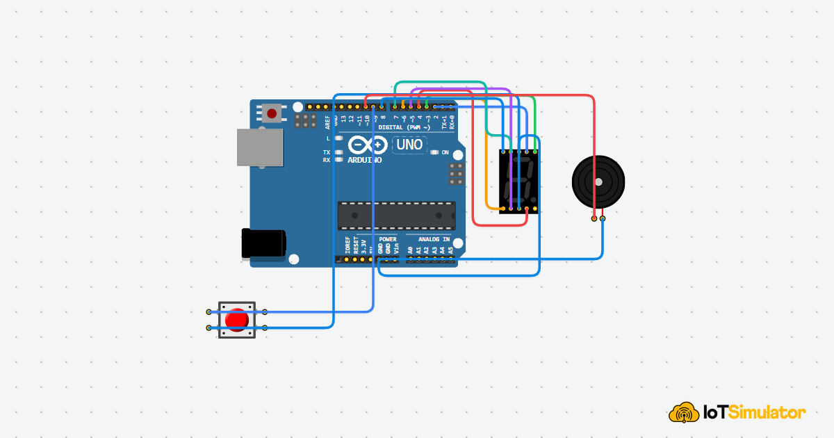
This circuit shows a simple Arduino Uno wired to a single 7-segment display. Each segment should use a current-limiting resistor, and the common pins should match the display type you are using.
For a common cathode display, connect the common pins to GND and drive the segment pins HIGH to light them. For a common anode display, connect the common pins to 5V and invert the segment logic.
Arduino Wiring
One beginner-friendly wiring map is shown below. It keeps the segment order easy to remember and works well for a single-digit demo.
| 7-Segment Pin | Arduino Uno |
|---|---|
A | Pin 2 |
B | Pin 3 |
C | Pin 4 |
D | Pin 5 |
E | Pin 6 |
F | Pin 7 |
G | Pin 8 |
DP | Pin 9 |
COM.1 | GND |
COM.2 | GND |
Current-limiting resistors are important here because each segment is still an LED. Without them, the display can draw too much current and behave unpredictably.
Code
This sketch cycles through 0 to 9 on a common cathode display. If your module is common anode, invert the output logic or switch the on and off values in the helper function.
The example is intentionally simple so you can see the segment logic clearly. Once this works, you can adapt it into counters, clocks, or sensor readouts.
How The Code Works, Part By Part
Let's break the sketch into smaller parts so it is easier to understand and easier to modify later.
Pin Setup
First, the Arduino prepares the eight segment pins and sets them as outputs. That lets the sketch control each LED bar one by one.
Digit Table
The digit table stores the on and off pattern for each number. Every row represents one digit, and every column represents one segment from A to DP.
Showing One Number
The showDigit() helper reads one row from the table and writes the state to each segment pin. If the display is common anode, the logic is flipped before the pins are written.
Looping Through Numbers
The loop steps through the numbers one by one so you can see each digit on the display. In a real project, this same idea could be used to show counts, sensor values, or countdown timers.
Using Multiple Digits
Multi-digit displays use the same segment logic, but the wiring changes because the digits are scanned one at a time. The segment lines are shared, and each digit gets its own enable line so the controller can choose which digit should be active at any moment.
This technique is called multiplexing. STMicroelectronics describes a four-digit example where eight lines drive the segment and decimal point signals while four more lines select the digits through transistors. The same note also points out that the refresh rate needs to be high enough to avoid flicker, and shows a 5 ms-per-digit cycle that produces about a 50 Hz update rate.
Multiplexing
The controller writes the pattern for one digit, enables that digit briefly, then moves to the next one. Your eyes blend those quick updates into one steady number, which is why the display looks continuous even though only one digit is actually on at a time.
That approach keeps the wiring manageable for larger displays, because the segment lines are shared instead of duplicated for every digit. It is the standard way to handle two-digit, three-digit, and four-digit modules.
Refresh Rate
The refresh needs to be fast enough that the display does not flicker. The ST application note recommends at least 25 refresh cycles per second to avoid flicker, and its example uses a 50 Hz update rate with roughly 5 ms per digit inside a 20 ms cycle.
That timing detail is what makes a multi-digit display feel stable. If the refresh is too slow, the digits can look dim or blink. If it is fast enough, the number appears solid even though the controller is scanning it internally.
Driver Notes
For bigger readouts, a dedicated display driver or a multiplexing helper can reduce the amount of manual scanning code you need to write. The important part is still the same: share the segment lines, select one digit at a time, and keep the refresh quick enough for a clean visual result.
Wrapping Up
The 7-segment display is one of the cleanest ways to show numbers in an embedded project. Once you understand the segment map and the common pin type, it becomes easy to use in counters, timers, clocks, and measurement tools.
From here, you can move on to 4-digit displays, multiplexing, or LED driver chips if you want a bigger readout. The basic logic stays the same, only the wiring and refresh method change.