This article is a guide about the DS1307 RTC. We will explain how it works, show how to wire it to an Arduino, and walk through a simple timekeeping example you can use in your own projects.
The DS1307 is useful when a project needs to keep the current time even after power is removed. That makes it a practical choice for clocks, loggers, reminders, and any build that needs a reliable timestamp.
Description
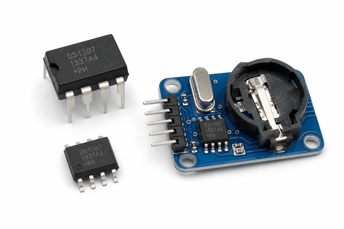
The DS1307 is a real-time clock, or RTC, module. It keeps track of seconds, minutes, hours, day, date, month, and year, so your Arduino project can remember time instead of starting over every time it restarts.
That makes it a very practical part for alarm clocks, timers, data loggers, calendars, and any project that needs a live clock or a saved timestamp. The chip can also keep counting when the main controller is off if a backup battery is present.
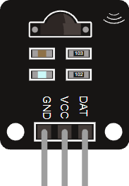
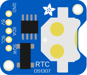
The photo below shows the DS1307 in a more close-up product style, which helps when you want to compare the chip package with the common breakout board you usually buy for Arduino projects.
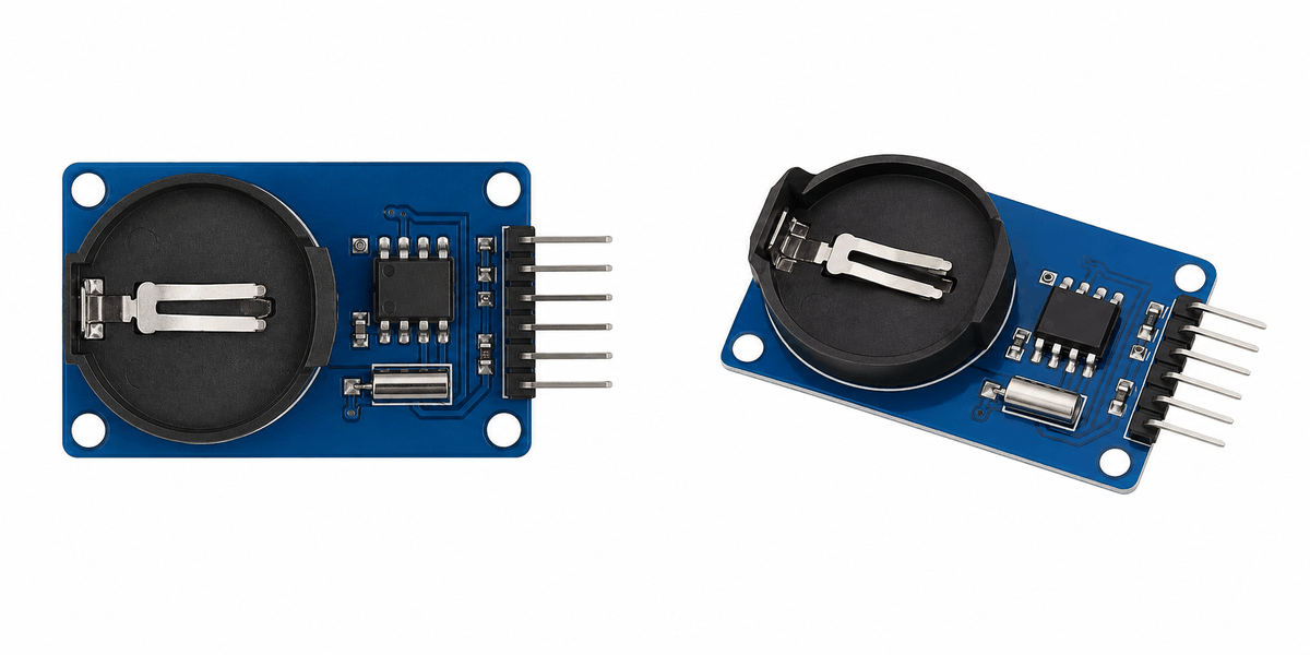
In a real build, the board usually talks to the Arduino through I2C, which keeps the wiring small while still letting the sketch read and update the current time whenever it needs to.
Features
Here are the main things to know about the DS1307:
| Feature | What it means |
|---|---|
| Real-time clock | Keeps date and time information running continuously. |
| I2C interface | Uses SDA and SCL for simple communication. |
| Backup battery | Can keep time even when the main power is removed. |
| Square wave output | SQW can generate timing pulses for other circuits. |
| Register-based time data | Stores seconds, minutes, hours, day, date, month, and year internally. |
| Beginner friendly | Easy to read with the RTClib library. |
The useful part is that the module gives your sketch a real time source instead of forcing it to count from zero every time the board resets. That is why it feels much more like a clock chip than a simple sensor.
How Does It Work?
The DS1307 contains an internal clock that counts seconds and rolls those counts into minutes, hours, and full calendar values. The Arduino asks the chip for the current time over I2C, and the chip returns the stored date and time values.
If a coin-cell battery is attached, the RTC keeps time even when the Arduino is turned off. That is why it is so useful for projects that need a clock that survives power loss.
In the Wokwi simulator, the DS1307 starts with the current system time and keeps counting. That makes it easy to test a clock sketch, a date display, or a simple alarm feature.
Time Keeping
The chip tracks the calendar in a set of internal registers. Your sketch does not need to count every second by hand, because the RTC keeps the values moving even when the board is busy doing something else.
Battery Backup
The coin-cell backup is what keeps the DS1307 useful after a reset or power loss. Without that battery, the chip can still work, but it will not remember the clock state once power disappears.
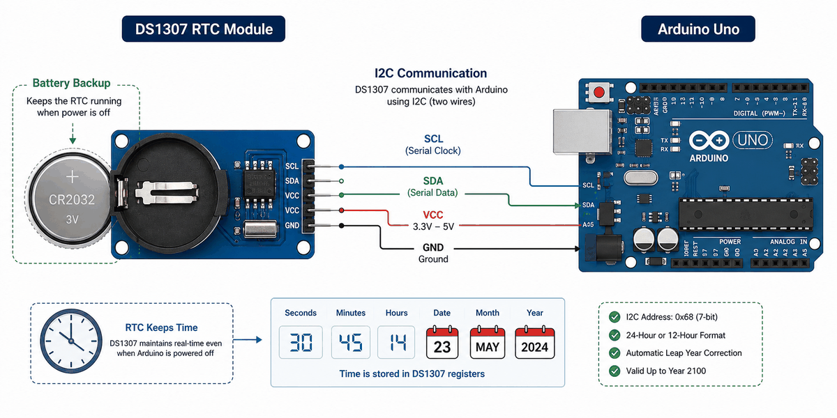
I2C Link
The Arduino talks to the DS1307 through SDA and SCL. That two-wire link keeps wiring simple and is the reason this module is easy to use with an Arduino Uno.
Arduino With DS1307
The Arduino setup is simple: the RTC uses I2C for time data, and the optional SQW pin can be used if you want a periodic pulse. In this example, the module is wired to the same I2C pins used by the Arduino Uno, which matches the sketch below.
A common use case for this setup is a clock or data logger that needs a timestamp on every reading. You can print the time in Serial Monitor, show it on an LCD, or attach it to sensor data so your project knows exactly when something happened.

Pin Connection
The pin connection is small, but each line has a specific role. Power and ground keep the module alive, and the I2C lines carry the time data between the RTC and the Arduino.
Shares the ground reference so the I2C signal stays stable.
Powers the DS1307 module.
Carries the I2C data line on an Arduino Uno.
Carries the I2C clock line on an Arduino Uno.
Optional square-wave output for timing pulses.
Most beginner examples only need power, ground, SDA, and SCL. The SQW pin is optional, but it can be helpful if you want a timing pulse for another part of the circuit.
Code
This example uses the RTClib library to read the current time and print it to Serial Monitor. It is a good first test for checking that the RTC is connected correctly and that the clock keeps running after reset.
The sketch prints a live date and time every second. Once it is working, you can display the result on an LCD, use it in a data logger, or trigger an alarm at a chosen time.
How The Code Works, Part By Part
Let's break the sketch into smaller pieces so the flow is easier to understand and easier to modify later.
Setup
The setup block starts the serial monitor, opens I2C, and checks whether the RTC is available. This is the first step before the sketch can read the current time.
Read The Current Time
This part asks the RTC for the current date and time. The returned value is stored in a DateTime object so the sketch can print or use it later.
Print The Time
Here the sketch prints the year, month, day, hour, minute, and second. That gives you a readable clock in the Serial Monitor and a simple way to check that the RTC is counting correctly.
Repeat
The loop repeats every second so the clock stays current. That rhythm is what turns the RTC into a live time display instead of a one-time reading.
Wrapping Up
The DS1307 is a useful RTC module when you need your Arduino project to remember time. It is simple to wire, easy to read, and works well in clocks and loggers.
Once you understand the I2C pins, battery backup behavior, and the time readout flow, you can use it confidently in projects that need accurate timestamps. If the time ever resets, the first things to check are the battery, the I2C wiring, and whether the sketch sets the clock after a power loss.
That small amount of setup gives you a reliable time source for the rest of the project, which is what makes the DS1307 so useful in real Arduino builds.