This article is a guide about the IR Receiver. We will explain how it works, show how to wire it to an Arduino, and walk through a simple example you can use in your own projects.
IR receivers are useful when a project needs to read commands from a TV-style remote or another infrared transmitter. The module filters the incoming infrared light and turns it into a clean digital signal, which makes the remote side useful instead of just invisible light in the air.
Description
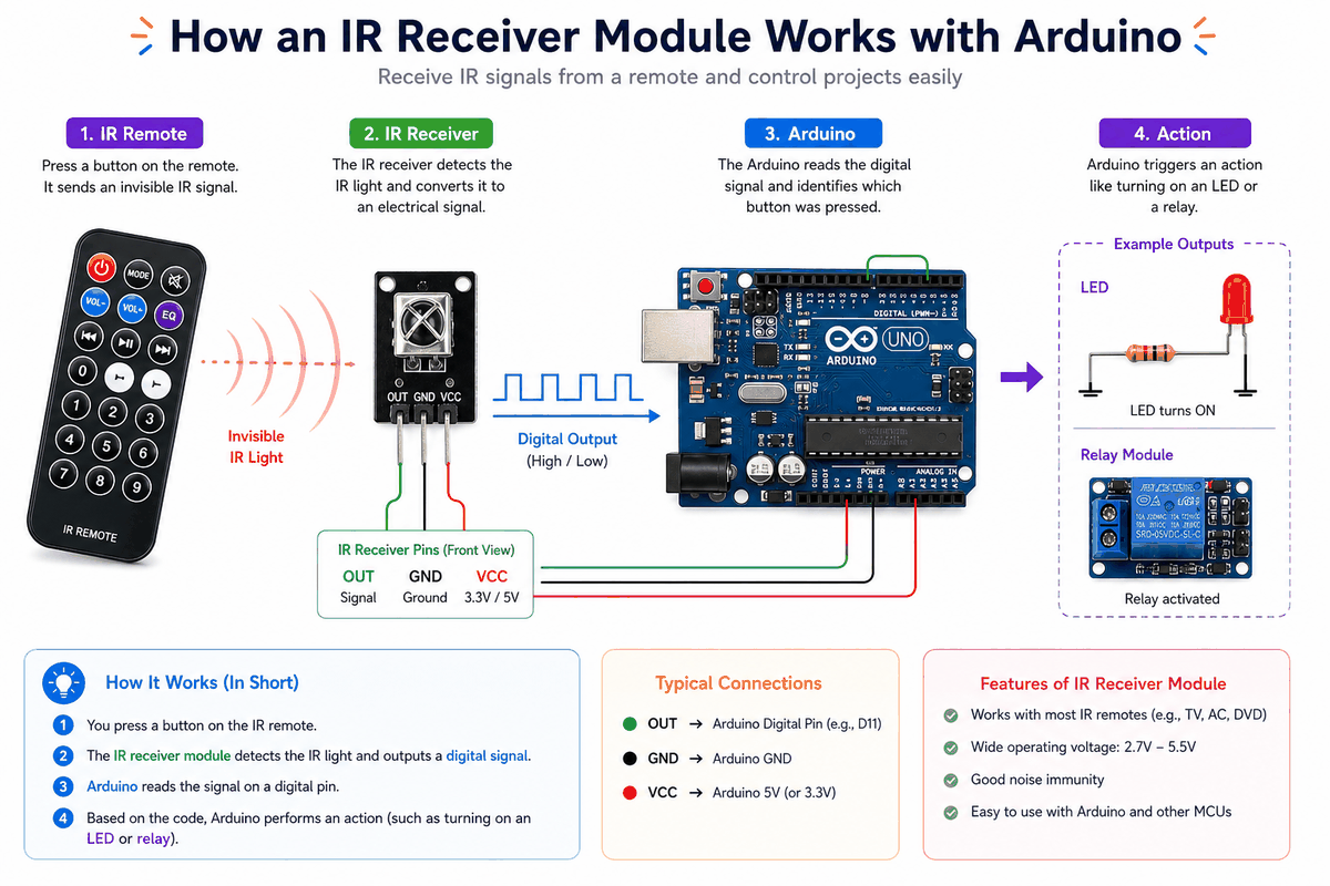
An IR receiver listens for infrared light that is usually modulated at around 38 kHz. When a matching signal arrives, the module decodes it and turns it into a digital output that the Arduino can read.
This makes it useful for remote-control projects, menu navigation, and simple wireless input. Instead of pressing a physical button on the board, you can point a remote at the receiver and let the sketch react to each command.
The IR Receiver and IR Remote belong together. If you want to understand the sender side too, read the IR Remote article and compare the two signal paths.
Features
Here are the main things to know about the IR Receiver:
| Feature | What it means |
|---|---|
| 38 kHz reception | Listens for the common infrared carrier used by remotes. |
| Digital output | Produces a decoded signal the Arduino can read. |
| Simple wiring | Usually only needs VCC, GND, and DAT. |
| Remote-friendly | Works well for buttons, menus, and wireless input. |
| Library support | Can be used with popular IR decoding libraries. |
The useful part is that the module turns invisible infrared pulses into data the sketch can react to.
How Does It Work?
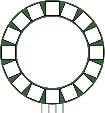
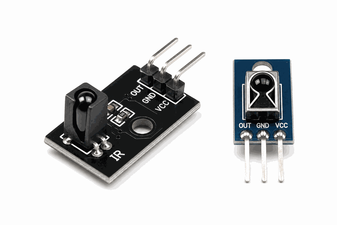
The sensor watches for infrared light from a transmitter or remote. Inside the module, the light is filtered and demodulated so the Arduino sees a clean digital signal instead of raw infrared flicker.
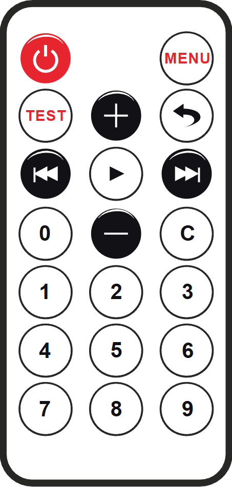
When a button on the remote is pressed, the sender transmits a structured code, often NEC-style in beginner examples. The receiver in the image sits in the middle of the signal path: it catches the incoming IR beam, strips away the carrier noise, and outputs a digital pulse that the sketch can read.
In the simulator, you can use the IR remote or click the receiver to send test messages. That makes it easy to practice decoding commands before you build a real remote-controlled project. Once the output reaches Arduino, the library translates the pulse pattern into a command value, which is the part your code actually uses.
Arduino With IR Receiver
The Arduino wiring is simple once you separate the power pins from the signal pin. The receiver only needs three connections, and the sketch listens on one digital input to catch the decoded command.

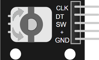
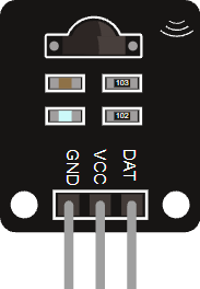
Pin Connection
The connection map is simple: connect VCC to the supply voltage, GND to ground, and DAT to a digital input pin such as D2. The Arduino reads the decoded infrared data from that single signal line.
Powers the receiver module so it can detect and filter infrared signals.
Gives the receiver and Arduino the same electrical reference.
Sends the decoded command as a digital signal that the sketch can read.
Because the receiver already handles the modulation details, the sketch does not need extra analog pins or timing math. The library takes care of most of the decoding work for you.
Code
This example uses the IRremote library to read commands and print the decoded value to Serial Monitor. The IR Receiver and IR Remote use the same library because they both speak the same infrared protocol, so one side sends the coded message and the other side decodes the same format.
The sketch prints each received IR command in a short format. From there, you can compare the codes and decide which button should trigger an LED, relay, display, or menu action.
How The Code Works, Part By Part
Let's break the sketch into smaller pieces so the flow is easier to understand and easier to modify later.
Setup
The setup block starts Serial Monitor and begins the IR receiver on the chosen pin. This is where the sketch gets ready to listen for remote commands.
Read A Command
This part checks whether a new infrared message has arrived. If the receiver has something to decode, the sketch reads and prints it.
Repeat
The loop keeps listening so the Arduino can respond to more button presses. After each decode, resume() prepares the receiver for the next code.
Wrapping Up
The IR Receiver is a simple way to bring remote control input into an Arduino project. It is small, practical, and useful for menu control, wireless buttons, and other easy automation ideas.
Once you understand the DAT pin and the decode flow, the real advantage becomes clearer: the receiver gives your sketch a clean command stream, and the IR library turns that stream into button actions you can use for LEDs, relays, displays, or menu navigation.
That is why this module is such a common starting point for IR projects. It keeps the wiring simple, the code readable, and the behavior easy to test before you move the idea into a real remote-controlled build.