This article is a guide about the Arduino Mega. We will explain how it works, show its pinout, and walk through an Arduino example you can use in your own projects.
The Mega is a good choice when a project grows beyond a small starter board. It gives you many more pins, more memory, and more hardware serial ports, which makes it useful for bigger builds that connect several sensors, displays, or communication modules at the same time.
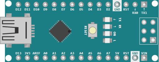
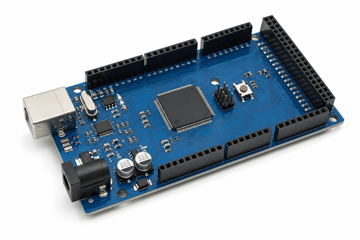
Before looking at the pin details, it helps to see the board itself first so the size, connector layout, and overall structure are easier to understand.
Description
The Arduino Mega is a microcontroller board based on the ATmega2560. It is designed for projects that need a lot of I/O space, so it is often used when an Uno would run out of pins or memory too quickly.
According to Arduino's official board documentation, the Arduino Mega includes 54 digital I/O pins, 16 analog inputs, 15 PWM outputs, and 4 UARTs. That mix makes it a practical board for larger projects that still want the familiar Arduino workflow.
Its bigger pin count also makes wiring easier in projects with many modules. Instead of stacking several boards or running out of shared pins, you can keep more connections on one controller and still stay in the Arduino ecosystem.
Features
Here are the main things to know about the Arduino Mega:
| Feature | What it means |
|---|---|
| ATmega2560 | Main microcontroller for the board |
| 54 digital I/O pins | More room for sensors, switches, and outputs |
| 16 analog inputs | Good for multiple sensor readings |
| 15 PWM outputs | Useful for dimming and motor control |
| 4 hardware serial ports | Better for GPS, Bluetooth, and other serial devices |
| 16 MHz clock | Standard timing for Arduino AVR code |
| 5V board | Matches many common Arduino sensors and modules |
The board is especially helpful when a project needs both many pins and several communication options. That is one of the biggest reasons people choose the Mega for large sensor arrays, control panels, and multi-device systems.
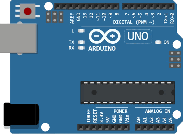
Arduino Mega vs Uno vs Nano
The Mega, Uno, and Nano all belong to the same Arduino family, but they solve different problems. The Uno is the balanced everyday board, the Nano is the compact breadboard-friendly option, and the Mega is the high-capacity choice when a project needs more room for pins, sensors, and communication devices.
Total Pins and I/O Capacity
The first big difference is how much I/O space each board gives you. The Uno is fine for small projects, but the Mega becomes much more comfortable when a circuit starts growing beyond a few LEDs or sensors.
| Board | Digital I/O | Analog Inputs | PWM Outputs | Main Takeaway |
|---|---|---|---|---|
| Arduino Uno | 14 | 6 | 6 | Good for starter builds and small prototypes. |
| Arduino Mega | 54 | 16 | 15 | Best when you need a much larger pin budget. |
The Nano stays compact, so it is often chosen for size first and pin count second. The Mega is the opposite: it is chosen when the project needs plenty of pins first, then size second.
Analog Inputs for Sensor Projects
Analog inputs matter when the project reads knobs, joysticks, light sensors, temperature sensors, or any other part that sends a changing voltage. This is where the Mega clearly pulls ahead.
| Board | Analog Inputs | What That Means |
|---|---|---|
| Arduino Uno | 6 | Enough for basic sensor work and simple control projects. |
| Arduino Nano | 8 | Slightly more analog room in a very small footprint. |
| Arduino Mega | 16 | Great for sensor-heavy projects and wider monitoring systems. |
If you are building a dashboard, data logger, or multi-sensor controller, the Mega gives you much more breathing room before you have to split the design across multiple boards.
PWM Outputs for Dimming and Motor Control
PWM is useful when you need dimming, speed control, or a smoother output than a simple on or off signal. The Mega gives you a lot more PWM-ready pins than the Uno or Nano.
| Board | PWM Outputs | What That Means |
|---|---|---|
| Arduino Uno | 6 | Works well for simple LED dimming and a few control channels. |
| Arduino Nano | 6 | Similar PWM space to the Uno, but in a smaller board size. |
| Arduino Mega | 15 | Better for multiple dimmable outputs, motor drivers, and larger control systems. |
Hardware Serial Ports for Communication
Communication is another area where the Mega stands out. It provides four hardware serial ports, which makes it easier to use GPS, Bluetooth, and other serial modules without fighting over the same line.
| Board | Hardware Serial Ports | Main Takeaway |
|---|---|---|
| Arduino Uno | 1 | Simple serial debugging and one main UART connection. |
| Arduino Nano | 1 | Compact board, but still limited to one main hardware UART. |
| Arduino Mega | 4 | Best when multiple serial devices need to work together. |
Board Size and Breadboard Fit
The physical size is the easiest difference to spot. The Nano is tiny and breadboard friendly, the Uno is a medium-sized all-rounder, and the Mega is much larger because it is built to carry more connections.
| Board | Official Size | Main Takeaway |
|---|---|---|
| Arduino Nano | 18 x 45 mm | Best for compact layouts and breadboard prototypes. |
| Arduino Uno | 68.6 x 53.4 mm | Balanced size for general learning and prototyping. |
| Arduino Mega | 101.52 x 53.3 mm | Largest of the three, but the extra size supports more I/O. |
So the short version is simple: use the Nano when space is tight, the Uno when you want a familiar middle ground, and the Mega when the project is large enough that pin count and serial connections matter more than compact size.
Board Overview
The Arduino Mega works like a bigger Arduino controller. The ATmega2560 runs your sketch, reads inputs, and drives outputs, while a separate USB interface chip handles uploading and serial communication from your computer.
Because the board has more pins than an Uno, it can connect many devices at once without forcing you to reuse the same I/O line for everything. That is especially helpful in projects where one board needs to watch sensors, control outputs, and still talk to a computer or another module.
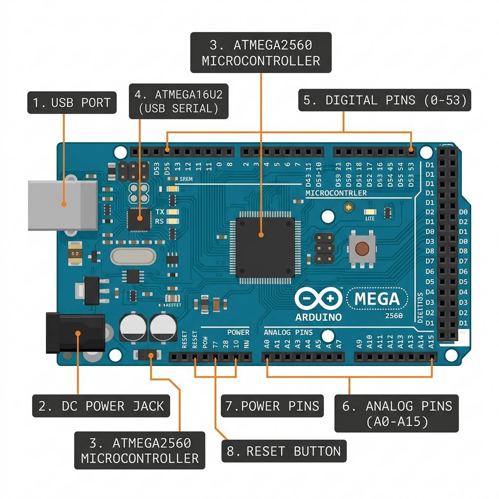
Main Controller
The ATmega2560 is the heart of the board. It stores your sketch, executes the code line by line, and manages the digital and analog pins that your circuit uses.
In everyday projects, this is the chip that decides when an LED turns on, when a sensor value is read, or when a communication message should be sent. The board is bigger, but the programming style still feels like normal Arduino code.
USB Bridge And Uploading
The Mega also includes a USB-to-serial interface chip. That chip lets your computer upload sketches to the board and open the Serial Monitor without needing extra hardware.
This is important because it keeps the workflow simple. You write code in the IDE, click upload, and the board receives the program through the USB connection just like other Arduino boards.
Pin Groups And I/O Layout
The Mega organizes its pins into useful groups. Some are digital pins for switches and outputs, some are analog inputs for sensors, and some are dedicated to communication buses such as I2C, SPI, and multiple UARTs.
That grouping is one reason the board feels practical in larger projects. You can keep sensor inputs, serial devices, and high-level control lines organized instead of running out of room on a small controller.
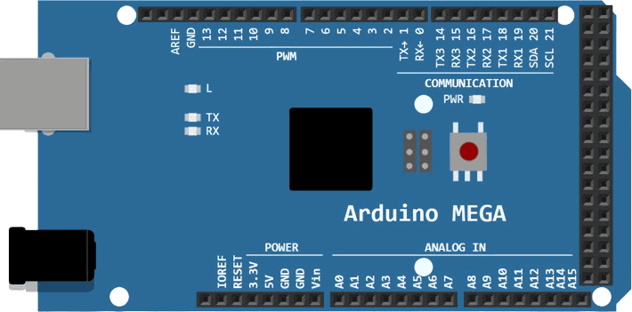
Pinout
The Mega's pinout is wider than the Uno's, which is why it is so useful for complex builds. The top edge carries the main digital pins, the right side holds the extra digital pins, and the bottom edge carries power, analog, and communication-related pins.
| Pin Group | What it is used for |
|---|---|
D0-D21 | Primary digital pins, including serial and PWM-capable lines |
D22-D53 | Extra digital pins for larger circuits |
A0-A15 | Analog inputs for sensors and variable signals |
5V, 3.3V, GND, VIN | Power and reference connections |
SDA/SCL | I2C communication |
50-53 | SPI communication |
The official pinout also shows the four hardware serial ports, which are one of the Mega's best-known advantages. That makes the board more comfortable for projects that need a GPS module, Bluetooth module, or another serial device at the same time as the main USB serial connection.
Arduino Mega With Other Components
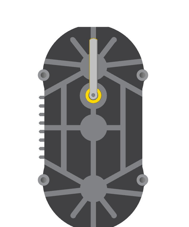
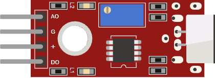
In bigger projects, the Mega is often paired with a mix of LEDs, buttons, sensors, displays, servo motors, stepper drivers, relay modules, and serial devices like GPS or Bluetooth. The extra pins and extra hardware serial ports make it easier to keep all of those parts on one board.
| Common Part | Why It Is Used With The Mega |
|---|---|
| LEDs and resistors | Quick visual status checks and output testing. |
| Buttons and switches | Simple input controls for menus and triggers. |
| LCD and OLED displays | Useful for dashboards, counters, and live feedback. |
| Servo and stepper drivers | Good for motion control and multi-axis projects. |
| Relay modules | Switch higher-power loads with safe isolation. |
| GPS and Bluetooth modules | Take advantage of the Mega's extra hardware serial ports. |
| Sensor arrays | The large pin count helps when many inputs are needed at once. |
That mix is what makes the Mega feel practical in real builds. It gives you enough room to organize the wiring instead of running out of pins too quickly.
Arduino Mega Wiring Example

This simple circuit is the classic first test for the Mega. It shows that the board can drive an output pin, power a resistor and LED, and still keep the normal Arduino programming flow you already know.
For a beginner test, wire one LED to pin 13 through a resistor and connect the LED cathode to ground. That gives you a fast way to confirm that the board, the code, and the simulator are all behaving correctly.
When you move on to larger projects, the same wiring habits still apply: give each device its own signal pin when possible, share ground across the whole circuit, and add current limiting wherever the component needs it.
Code
This example blinks the on-board style LED setup on pin 13 and prints the state to Serial Monitor. It is simple enough for beginners, but it still shows that the Mega behaves like a standard Arduino board.
You can change the pin number in the sketch if you want to test a different digital output. The large pin count on the Mega makes it easy to move from one pin to another when your project gets bigger.
How The Code Works, Part By Part
Let's break the sketch into smaller pieces so the flow is easy to understand.
Pin Setup
First, the sketch stores the LED pin number and sets it as an output. That tells the Mega this pin will drive something instead of reading it.
Turn On
When the pin goes HIGH, the board provides voltage to the LED path. If the LED is wired with the correct polarity and a current-limiting resistor, it lights up cleanly.
Turn Off
When the pin goes LOW, the voltage difference disappears and the LED turns off. That simple on/off control is the foundation of many Arduino output projects.
Repeat
The loop() function keeps running forever, so the board repeats the blink pattern automatically. That is what makes the LED flash continuously until you change the sketch.
Wrapping Up
The Arduino Mega keeps the same friendly Arduino workflow while giving you far more pins and communication options. Once you understand the board layout, it becomes a very practical controller for bigger projects.
If you need a board that can manage many connections without losing the simplicity of Arduino code, the Mega is one of the most useful AVR choices in the lineup.