This article is a beginner-friendly guide to the SSD1306 OLED display. You'll learn what the chip does, why OLED screens look so crisp, what the pins usually mean, and how to wire and test one with an Arduino.
People like SSD1306 screens because they make a project feel "real" fast: sensor values, tiny menus, icons, and simple graphs all fit on a screen that only needs a handful of wires.
Description
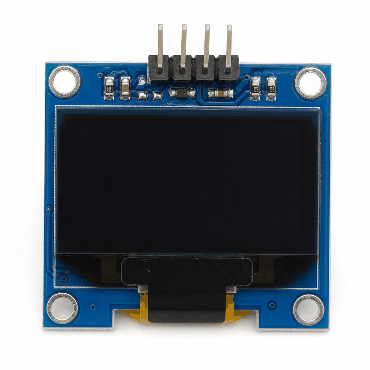
The SSD1306 is the controller chip that drives many small monochrome OLED modules (most commonly 128x64 pixels, sometimes 128x32). "Monochrome" means every pixel is either on or off. There is no color and no gray shades, but the contrast is great because OLED pixels make their own light.
Unlike a character LCD (which thinks in fixed rows and columns of letters), an SSD1306 screen is a true pixel display. Your code can put text anywhere, draw lines and boxes, and show small bitmap icons. That freedom is why SSD1306 screens are popular for simple menus, sensor dashboards, and small status panels while you build a project.
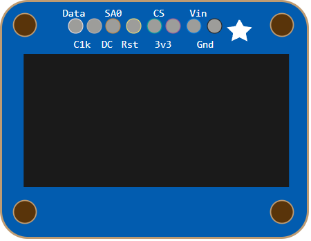
One thing that surprises beginners: SSD1306 modules are sold in different "pinout styles." Some are I2C (4 pins) and some are SPI (7-8 pins). In this simulator, the SSD1306 part exposes the SPI-style pins (DATA/CLK/DC/CS/RST plus power), so the wiring and code examples below focus on SPI. After that, we'll explain I2C so you can recognize both in real life.
Features
Here are the main things to know about the SSD1306, written in a practical way (what you will actually notice while building):
| Feature | What it means |
|---|---|
| Monochrome OLED pixels | Bright "on" pixels on a true dark background (great contrast). |
| 128x64 (typical) | Common resolution for 0.96-inch modules; some modules are 128x32. |
| Pixel drawing (graphics) | You can draw text, lines, boxes, icons, and custom layouts. |
| Uses a display buffer | Most libraries draw into RAM first, then send a full frame to the screen. |
| SPI or I2C (module dependent) | SPI uses more pins but often refreshes faster; I2C uses fewer pins. |
| I2C addresses (common) | Many I2C modules show up at 0x3C or 0x3D. |
If you are using an Arduino Uno, the "buffer" detail matters. A 128x64 monochrome screen needs a 1,024-byte framebuffer. That is a big chunk of the Uno's 2KB SRAM, so it is normal to keep graphics simple (text and a few shapes) and avoid huge bitmaps at first.
How Does It Work?
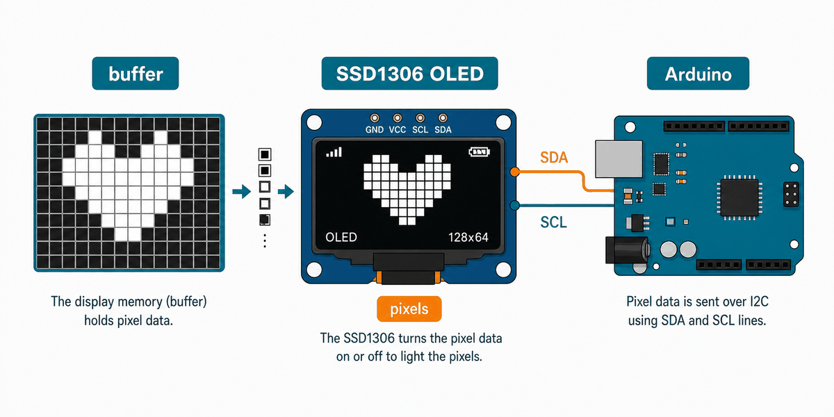
Most SSD1306 libraries work the same way. Your code draws into an off-screen buffer in RAM, and then you call a single function (often display.display()) to send that whole buffer to the OLED. That is why the screen updates cleanly: you build the "next frame" first, then push it to the display in one go.
So when you write println(), you are not writing straight to the OLED instantly. You are writing into memory first. This mental model is useful because it explains two common surprises: (1) nothing shows up until you "push" the buffer, and (2) complex screens can feel slow because the library sends a lot of data every time you refresh.
Display Buffer (Why It Uses RAM)
A 128x64 screen has 8,192 pixels. Because it is monochrome (1 bit per pixel), the framebuffer is 8,192 / 8 = 1,024 bytes. On small boards, that means the display can be "cheap" in wiring but "expensive" in RAM. It is still worth it, but it explains why adding lots of fonts and bitmaps can suddenly make a sketch crash or act weird.
A simple way to picture it: the SSD1306 packs pixels into bytes. One byte can represent 8 pixels (on/off). The library handles that packing for you, but it helps to know why "a screen" takes real memory.
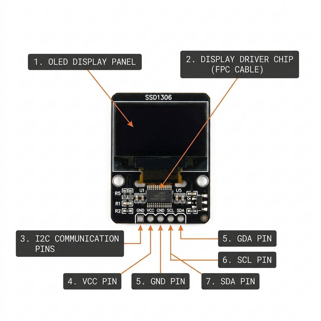
I2C Transfer (4-pin modules)
With I2C modules (the 4-pin style), the screen shares the same two wires (SDA/SCL) with other I2C sensors. The common addresses you will see are 0x3C and 0x3D. If your code says the display was not found, the first thing to check is the address and wiring.
SPI Transfer (7-8 pin modules)
With SPI modules (the 7-8 pin style), the screen uses a clock line and a data line plus a few control pins. The wiring uses more pins than I2C, but updates are usually faster and can feel more reliable when you redraw the screen often (like a live sensor dashboard).
Quick Pin Label Cheat Sheet (So You Don't Guess)
Real modules do not always use the same pin names. Here is a quick translation so you do not get stuck when a seller listing uses different labels.
| You might see... | It means... |
|---|---|
VCC or VIN | Power input (often 3.3V to 5V on hobby modules, depending on the board). |
GND | Ground (the return path for current). |
CLK, SCK, or D0 | SPI clock. |
DATA, MOSI, or D1 | SPI data from the board to the display. |
DC or A0 | Data/Command select (tells the display what kind of bytes are coming next). |
CS | Chip Select (selects the display on the SPI bus). |
RST or RES | Reset (brings the display into a known state). |
SDA + SCL | I2C data + clock (only on 4-pin modules). |
Arduino With SSD1306 (Simulator Wiring)
This circuit preview shows the SSD1306 wired to an Arduino Uno using the SPI-style pins exposed by the simulator component: DATA, CLK, DC, CS, and RST, plus power.

Pin Connection
The pin map below matches the circuit preview. Power and ground keep the module running, while the SPI lines carry the pixel data and the control pins tell the OLED whether the next bytes are commands or screen data.
Provides power to the OLED module.
Shares the ground reference with the Arduino.
Sends pixel data and commands into the display over SPI.
SPI clock line that times the data transfer.
Data/Command select: tells the display whether incoming bytes are commands or pixels.
Chip Select: lets the Arduino talk to the OLED on the SPI bus.
Resets the OLED so it starts in a known state.
In real modules, the labels sometimes vary. You might see D0/D1 instead of CLK/DATA, or SCK/MOSI. The idea stays the same: one pin is the clock, one pin is the data, and the display uses DC/CS/RST as control lines.
Code
This example shows a title and a small status message on the OLED. It is a simple first test that proves the display is powered, wired correctly, and receiving SPI data.
From here you can replace the sample text with sensor values, menu items, or a custom graphic depending on what your project needs. Once the screen is working, it becomes one of the easiest ways to make a project feel finished.
Try This Next: A Simple Progress Bar
Once you can print text, a nice next step is drawing a small bar. This makes it easy to show things like "battery", "volume", or "distance" without reading tiny numbers.
How The Code Works, Part By Part
Let's break the sketch into smaller pieces so the display workflow is easier to understand and easier to modify later.
Libraries
The sketch uses SPI for communication and the Adafruit display libraries for graphics and SSD1306 control. Adafruit GFX provides drawing tools (text, lines, rectangles). Adafruit SSD1306 handles the low-level display protocol.
Display Object
The display object describes the screen size and tells the library which pins to use for DC, RST, and CS. The actual SPI data and clock lines use the Arduino Uno's hardware SPI pins (MOSI and SCK).
Setup
In setup(), the sketch initializes the OLED. If the display does not respond, the code prints an error and stops. Then it clears the buffer, draws a couple of text lines, and finally pushes the buffer to the screen.
Show Frame
The display.display() call sends the drawn buffer to the OLED. That is the step that makes the text or graphics appear on the screen.
Repeat
This simple example does not need a repeating animation loop, because the first frame stays on the screen until the sketch changes it. In a real project, it is common to update the display a few times per second so you do not waste time sending the same frame hundreds of times.
Common Issues (and Fast Fixes)
- Nothing shows up: verify power and GND first, then double-check CLK/DATA pins. For SPI, remember that Uno hardware pins are
D13(SCK) andD11(MOSI). - Text draws but looks "frozen": you probably forgot
display.display(). The library draws into RAM first, then pushes to the screen. - Works on one module but not another: some cheap OLEDs are actually SH1106 (not SSD1306). They look similar, but need a different driver library.
- I2C module not found: try address
0x3Cvs0x3Dand confirm SDA/SCL go to the correct pins. - Random pixels or flicker: make sure RST is wired (or your module has auto-reset), and avoid loose jumper wires.
Wrapping Up
The SSD1306 is one of the best "first displays" because it is small, readable, and flexible. Once you get the idea of drawing into a buffer and then pushing a frame to the screen, you can build clean little UIs: sensor panels, menus, status indicators, even tiny graphs.
In this simulator, the SSD1306 uses the SPI-style pinout (DATA/CLK/DC/CS/RST). In real life, you will also see 4-pin I2C versions, usually at address 0x3C or 0x3D. If you can recognize both, you will be able to wire almost any SSD1306 module you buy without guessing.