This article is a guide about the Stepper Motor. We will look at why it moves in steps, how the coil sequence creates motion, and how to wire it for an Arduino demo.
Stepper motors are useful when a project needs repeatable rotation instead of simple on/off motion. They let you count movement in steps, so the shaft can stop at a predictable angle instead of just spinning freely.
Description
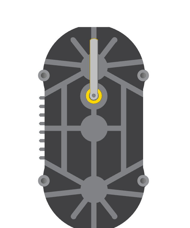
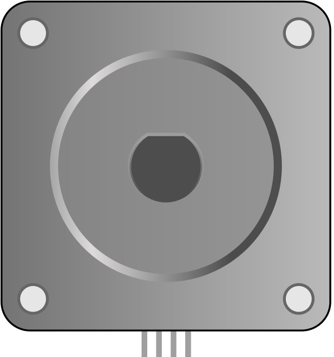
The stepper motor is a bipolar motor that moves in small, repeated steps. In the simulator, it appears as a clear motion part with four coil connections, which makes it easier to see how step-by-step control works.
That makes it a great learning part for projects such as position control, small motion platforms, rotating indicators, and simple automation demos. Instead of spinning freely like a DC motor, a stepper motor moves in measured steps, which gives the Arduino better control over position and direction.
A common hobby stepper moves 1.8 degrees per step, which means about 200 steps make one full rotation. That step-based behavior is exactly what makes it useful when you want precise movement.
Features
Here are the main things to know about the Stepper Motor:
| Feature | What it means |
|---|---|
| Step-based movement | Moves in fixed increments instead of free spinning. |
| Good position control | Lets code move the shaft by a known number of steps. |
| Bipolar coil layout | Uses two coil pairs to create magnetic motion. |
| Simulation friendly | Easy to watch motion changes in the circuit preview. |
| Works with libraries | Can be driven by the Arduino Stepper library or driver-based libraries. |
The key advantage is repeatable movement, which makes the motor very useful for controlled rotation projects. You can ask for a specific number of steps and get a matching amount of motion instead of hoping the shaft lands in the right spot.
How Does It Work?
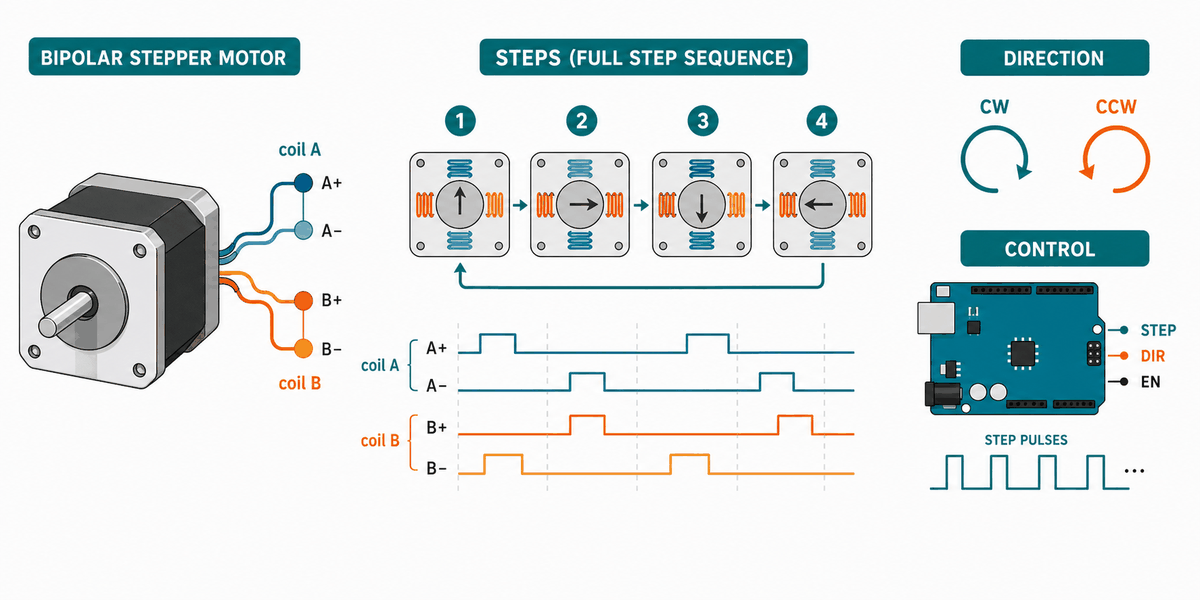
The stepper motor works by energizing its coils in a sequence. Each pulse changes the magnetic field a little, and that change moves the shaft one step at a time. When the sequence repeats, the shaft keeps turning in a controlled direction.
If the sequence changes direction, the motor turns the other way. If you change the speed of the sequence, the motor moves faster or slower. That is what gives the Arduino very fine control over motion.
Unlike a simple buzzer or LED, the motor keeps track of position through steps. That is why the code must send the right coil pattern in the right order.
Coils And Phases
The two coil pairs work together to produce motion. When one pair energizes and then the next pair follows, the motor shaft advances to the next step.
Step Sequence
The order of the coil pulses matters. A correct sequence makes the shaft turn smoothly, while a wrong order can make the motor jitter or move backward.
Common Use Case IOT
Stepper motors show up in projects where precise rotation matters more than speed. They are common in 3D printers, small plotters, camera sliders, valve controls, turntables, and automatic feeders because those jobs need repeatable motion instead of free spinning.
In IoT-style builds, a stepper can move a camera toward the right angle, open a small vent, rotate a display, or advance a mechanism by a fixed amount. That makes it useful when a sensor or app command needs to become a visible physical action.
People also use stepper motors when they want a project to stop in the same place every time. That predictable stopping behavior is the real reason the motor is so popular in positioning systems and small automation projects.
Arduino With Stepper Motor
This circuit preview shows the stepper motor connected to Arduino Uno through a driver-style coil setup. It is the right way to think about a stepper project because the Arduino controls the sequence, while the coils do the heavy lifting.

Pin Connection
The pin map below matches the circuit preview. The two coil pairs need to stay together so the stepping sequence stays smooth and the direction stays predictable.
One side of the first coil pair.
The other side of the first coil pair.
One side of the second coil pair.
The other side of the second coil pair.
With a stepper, the Arduino does not power the coils directly in a real build. A driver board is usually used so the motor can get enough current without stressing the microcontroller pins.
Code
This example uses the Arduino Stepper library to move the shaft a full revolution, pause, and then reverse direction. It is a simple way to see that the motor is really stepping through position.
That sketch is a good first test because it shows both direction control and full-turn movement with a small amount of code. When it works, you know the coil order and step count are lined up correctly.
How The Code Works, Part By Part
Let's break the sketch into smaller pieces so the flow is easier to understand and easier to modify later.
Library And Step Count
The sketch starts by loading the Stepper library and defining how many steps are needed for one full rotation. That number is the foundation for all the movement that follows.
Create The Motor Object
Next, the code creates a Stepper object and gives it the four coil pins. This tells the library which pins to energize in order to move the shaft.
Set Speed
The setup block sets how fast the motor should move. A higher value makes the shaft step faster, while a lower value makes it easier to watch the motion.
Move Forward
The first move call turns the motor one full revolution in the forward direction. This is the part that proves the stepping sequence is working.
Move Backward
The second move call reverses the direction by using a negative step value. That shows how the same motor can move both ways with simple code changes.
Repeat
The loop keeps alternating forward and backward movement so you can watch the shaft respond clearly in the simulator.
Wrapping Up
The Stepper Motor is a strong choice when you want code-controlled movement with predictable position changes. It is especially useful when the project needs to stop at a known angle or move in small, repeatable increments.
Once you understand the coil sequence, the step count, and the direction control, you can use the motor confidently in rotation and positioning projects. That makes it one of the most practical actuators for learning precise motion in Arduino work.