This article explains the Potentiometer in a practical way: what it does, how it creates a variable voltage, how to wire it, and how to read it from Arduino code.
Potentiometers are common in beginner projects because they turn a simple knob movement into a value the board can understand.
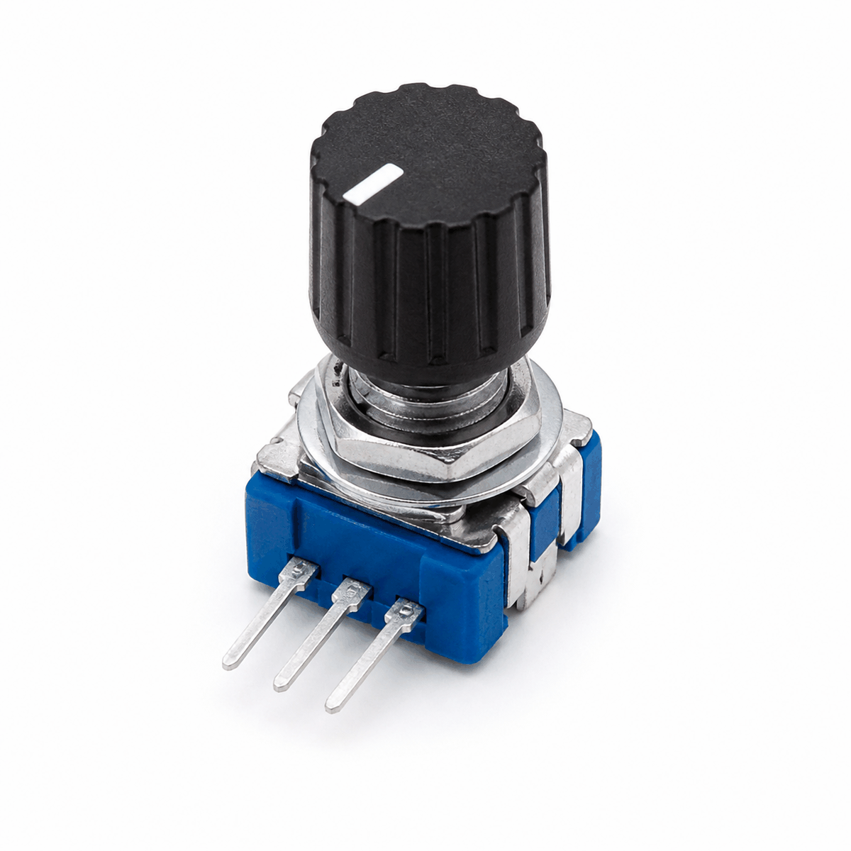
Description
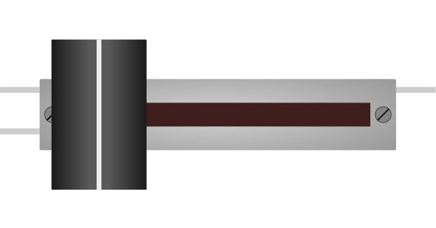
The potentiometer is a variable resistor. When you turn the knob, the resistance changes and the middle pin outputs a voltage that changes along with it. That makes it a classic example of an analog input device.
Arduino boards use that changing voltage as a reading between 0 and 1023 on a 10-bit analog input. That is why the potentiometer is often the first part people use when learning analogRead().
It is also useful in real projects for volume knobs, speed controls, menu selectors, brightness controls, and other places where the user should be able to adjust a value smoothly.
Potentiometer vs KY-040
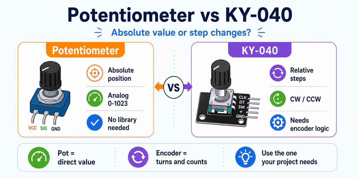
A potentiometer gives an absolute analog position. When you turn it, the Arduino reads a changing voltage right away, so the value is always tied to the knob position.
A KY-040 rotary encoder works differently. It sends step and direction signals instead of a direct voltage, so the sketch counts turns rather than reading a fixed position.
That difference matters in real projects. Use a potentiometer when you want a direct value like brightness or volume. Use a KY-040 when you want to move through menus, count steps, or change settings with rotation instead of voltage.
Features
Here are the main things to know about the Potentiometer:
| Feature | What it means |
|---|---|
| Variable resistance | The resistance changes as you turn the knob. |
| Analog output | The middle pin gives the Arduino a changing voltage. |
| Easy to read | Works directly with analogRead(). |
| Common control part | Useful for user-adjustable values in projects. |
| Beginner friendly | One of the easiest analog input parts to understand. |
| Voltage divider | The knob naturally behaves like a simple divider. |
| Full range input | Usually maps to a 0 to 1023 analog value. |
The important part is that the knob gives you a smooth and predictable range of values instead of only on or off behavior.
How Does It Work?
The potentiometer works as a voltage divider. The two outer pins connect to power and ground, and the middle pin moves between those two voltages as you turn the knob. The Arduino reads that middle voltage and converts it into a number.
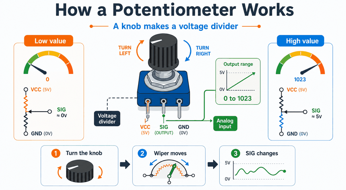
When the knob turns, the wiper moves along the resistive track. That changes how much voltage appears on the middle pin, so the reading climbs or drops instead of staying fixed.
This is the part that makes the potentiometer feel very intuitive. You are not switching between two states. You are moving across a range, and the Arduino sees that movement as a changing analog value.
Because the output changes smoothly, you can use it to control LED brightness, motor speed, menu selection, or any other value that should move gradually instead of jumping abruptly.
If the value moves in the opposite direction from what you expect, the outer pins are usually swapped. The center pin still stays on the analog input, but reversing the ends changes which way the reading rises.
That is why the potentiometer is one of the clearest ways to learn analog input. You can see the knob move, watch the reading change, and immediately connect the physical motion to the number in Serial Monitor.
Voltage Divider
The two outer pins form the ends of the resistive track. The center pin, often called the wiper, slides across that track and produces the adjustable output voltage.
In a simple Arduino setup, one side of the track sits at 5V and the other side sits at ground. The wiper samples a point between them, which is why the middle pin can give you a value anywhere across the range.
Analog Read Range
On an Arduino Uno, the analog reading goes from 0 to 1023. Turning the knob one way gives a lower value, and turning it the other way gives a higher value.
That 0 to 1023 range is useful because it is wide enough to map into brightness, speed, volume, or any other control value you want to tune smoothly in code.
Arduino With Potentiometer
This circuit preview shows a simple Arduino Uno connected to the potentiometer. It is a practical starting point because the analog value can be tested immediately and the knob response is easy to see.
You do not need a special library for a basic potentiometer project. The Arduino only needs to read the middle pin with analogRead(), so the sketch stays short and direct.
That is one reason the potentiometer is such a common beginner part. The hardware gives you the changing voltage, and the built-in Arduino function turns it into a number without extra setup code.

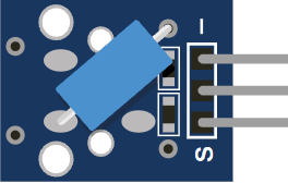
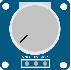
Pin Connection
The pin connection below matches the circuit preview. The middle pin is the signal pin, so that is the one to remember when you read the knob value in code.
Powers the resistor track inside the module.
Sends the adjustable analog voltage to Arduino.
Gives the circuit a shared electrical reference.
Because the signal is analog, the Arduino reads a changing value instead of a simple HIGH or LOW state. That makes the potentiometer a good first part for learning how analog input behaves.
Code
This example reads the potentiometer and prints the value to Serial Monitor so you can see the knob position change in real time.
Once that works, you can use the value to control brightness, speed, a menu, or any other adjustable setting in your project.
How The Code Works, Part By Part
Let's break the sketch into smaller pieces so the knob-reading flow is easier to understand and modify later.
Setup
The setup block starts Serial Monitor so you can watch the analog value change while turning the knob.
Read Value
The sketch reads the analog pin connected to the wiper. This gives a number that reflects the current knob position.
Print Value
Printing the number helps you verify that the potentiometer is wired correctly and that the value changes when the knob moves.
Repeat
The short delay keeps the serial output readable while the sketch continues checking the knob position.
Wrapping Up
The potentiometer is a simple but powerful input part when you need a smooth value from the user.
Once you understand the voltage divider idea, the analog range, and the center signal pin, you can use it confidently in menus, controls, calibration tools, and live adjustment panels.
It is one of the best first analog parts to learn because the change is visible on the knob and visible in the code at the same time. That makes it a very good bridge between hardware movement and software reading.