This article explains the Photoresistor Sensor in a practical way: what it does, how it reacts to light, and how to wire it to Arduino.
It is a good fit when a project needs to react to room brightness, from simple light meters to automatic lamps and night-light builds.
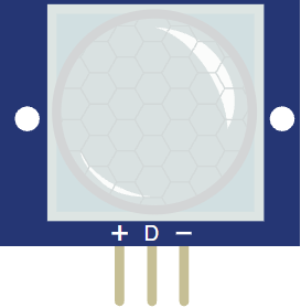
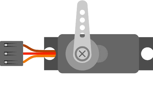
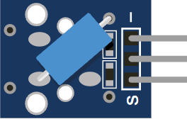
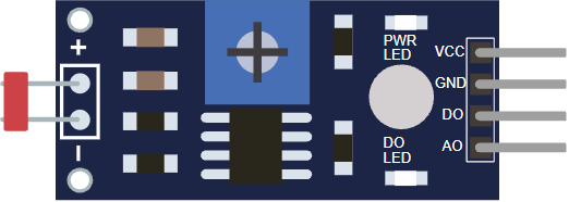
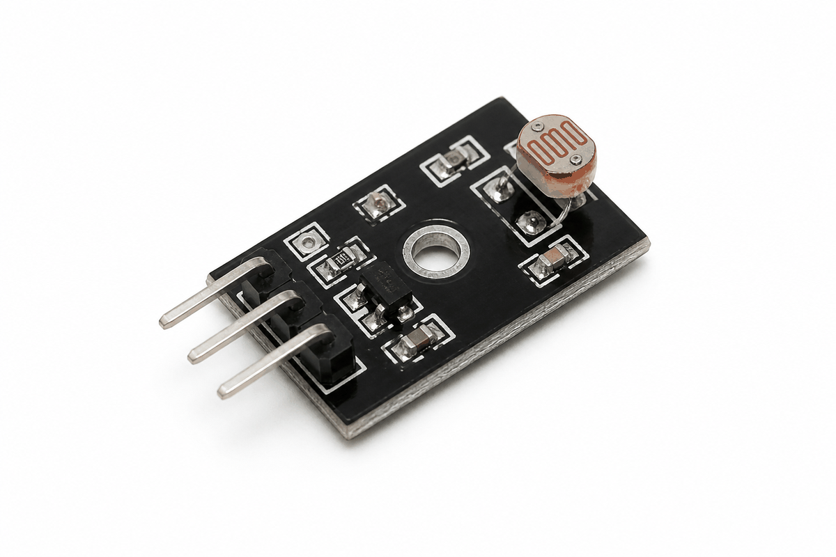
Before the circuit, it helps to see the module first so the body, board layout, and pin side are easier to picture.
Description
The photoresistor sensor module uses a light-dependent resistor, or LDR, to measure brightness. When light hits the sensor, its resistance changes, and the module turns that change into a voltage that Arduino can read.
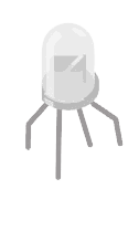
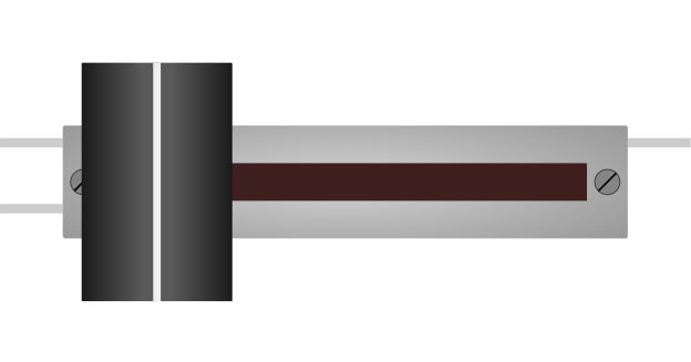
The same part also appears as a bare single photoresistor, and many module boards are sold as KY-018 style boards. The bare LDR is the raw sensor, while the module adds the resistors and output pins that make Arduino wiring easier.
That makes it a good beginner part for night lights, brightness meters, automatic lamps, and other small projects that react to room light.
Many modules give you both an analog output and a digital output. The analog output gives you the raw light reading, while the digital output acts like a threshold switch.
Photoresistors are better for coarse light sensing than precise lux measurement. They are not polarized, so the two sensor legs can connect either way.
Their response is slower than phototransistors or photodiodes, which is fine for a night light or room brightness monitor, but not ideal for fast light changes.
Different parts can behave a little differently, so the readings often need a quick calibration step. The module is useful because it shows a clear trend, not because every unit reads exactly the same.
Why KY-018 Exist
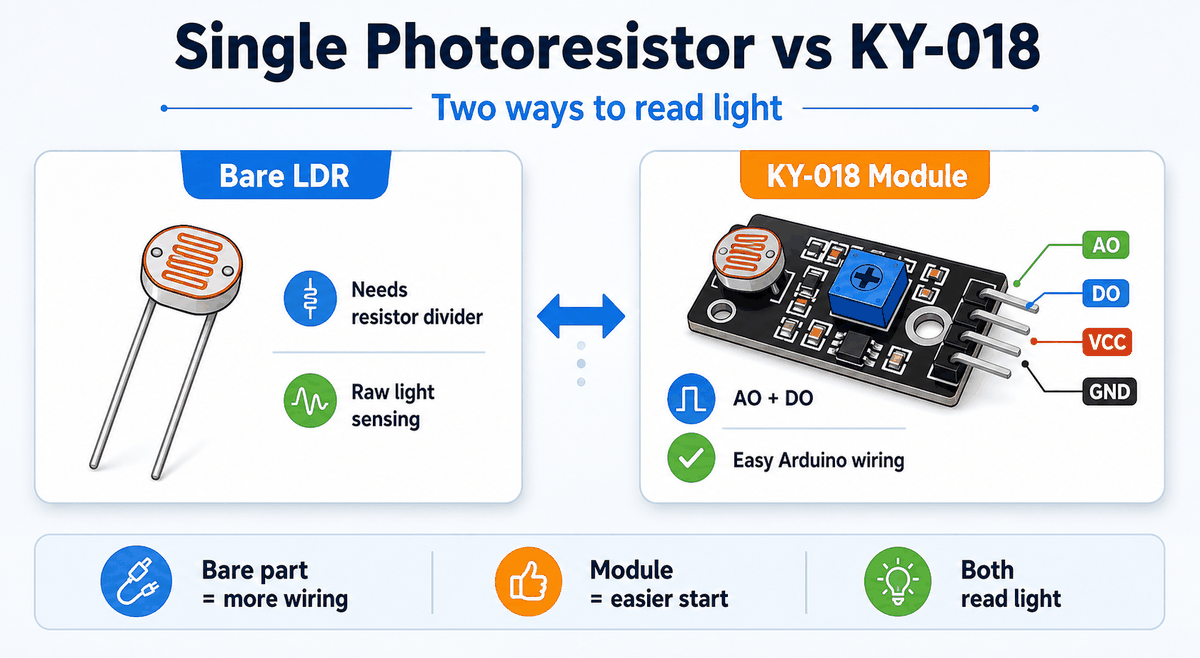
The KY-018 module exists to make the bare photoresistor easier to use with Arduino. The raw LDR only gives resistance change, so you still need a resistor divider and a clean way to read the signal.
The module adds that supporting circuit for you. That gives you a ready-to-use analog output, a digital threshold output, and pins that plug into a breadboard without extra guesswork.
The bare photoresistor still makes sense when you want to learn the circuit or build your own divider from scratch. The module makes more sense when you want faster setup, cleaner wiring, and less trial and error.
Features
Here are the main things to know about the Photoresistor Sensor:
| Feature | What it means |
|---|---|
| Analog output | Lets the Arduino watch brightness as a changing value. |
| Digital threshold output | Can trigger when the light crosses a set level. |
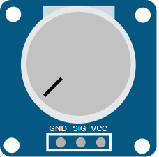
| Adjustable sensitivity | The onboard potentiometer changes the trigger point. |
| Simple wiring | Usually only needs power, ground, and one or two signal pins. |
| Beginner friendly | Good for light meters and automatic lamp demos. |
| Voltage divider behavior | Works naturally with analogRead(). |
| Coarse sensing | Best for light and dark changes, not precise lux values. |
| Non-polarized sensor | The bare LDR legs can be connected either way. |
| Slower response | Better for room sensing than rapid light changes. |
The most useful thing about the module is that it gives you both a live reading and a simple on or off light condition. That makes it flexible enough for beginner demos and small control projects.
If you need a more exact light measurement, a phototransistor or photodiode is usually the better choice. For automatic lamps, room sensing, and simple threshold logic, the photoresistor is still practical.
How Does It Work?
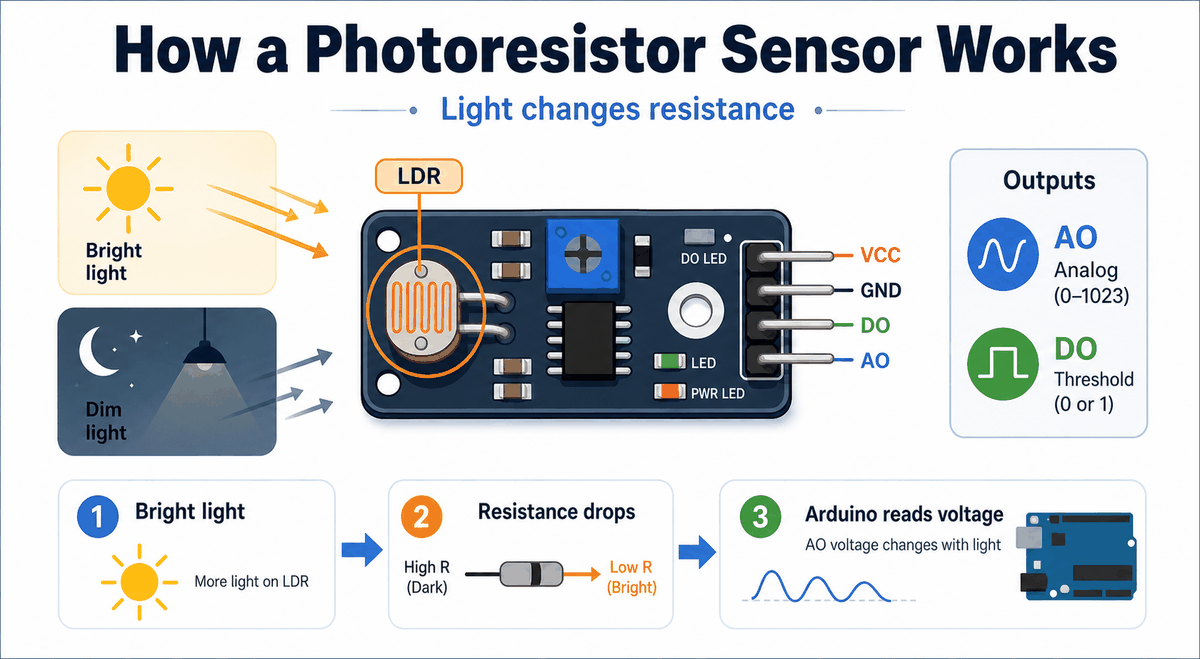
The LDR changes resistance depending on how much light reaches it. In bright conditions the resistance drops, and in darker conditions it rises. The module turns that change into an analog voltage on AO.
The Arduino reads that voltage with analogRead(). If the module also uses a comparator, the DO pin can switch based on a threshold set by the onboard potentiometer or simulator control.
Analog Reading
The analog output is the best choice when you want to see how the brightness changes in real time or map the reading to another output like an LED or servo. It gives you a smooth value, so the sketch can respond gradually instead of only jumping between two states.
Digital Trigger
The digital output is better when you only need a clean yes or no answer, such as turning on a lamp when it gets dark. It behaves more like a light switch, which is useful when the project only cares about crossing a threshold.
Photoresistor Sensor Pinout
The module exposes four pins: VCC, GND, DO, and AO. The analog pin is the one you use when you want the full light reading, while the digital pin is there for threshold-based behavior.
| Pin | Meaning | Beginner note |
|---|---|---|
VCC | Power supply | Usually connect to 5V. |
GND | Ground | Must share ground with the Arduino. |
AO | Analog output | Use this for the raw brightness reading. |
DO | Digital threshold output | Use this for an on/off light trigger. |
Arduino With Photoresistor Sensor
This circuit preview shows a basic Arduino Uno connection with the photoresistor module. It is a good starting point because the analog output can be tested immediately and the threshold output can be added later if needed.

Pin Connection
The connection table below follows the same wiring shown in the circuit preview. The analog pin is the main one to remember, and the digital pin is optional if you want threshold behavior.
Supplies power to the sensor module.
Shared ground reference for stable readings.
Carries the analog light reading into Arduino.
Optional digital trigger output for threshold use.
If the reading looks inverted, that is usually not a wiring failure. It means the module is changing in the opposite direction from what you expected, so the sketch may need a small adjustment to the threshold or mapping logic.
Arduino Code
This example reads the analog light value and prints it to Serial Monitor. It is the easiest first test for a photoresistor sensor because you can see the number change as the light changes.
About analogRead()
The analogRead() function turns the changing voltage into a number the sketch can use. On an Arduino Uno, the result usually ranges from 0 to 1023, which makes it easy to compare against a threshold or remap into another output.
How The Code Works, Part By Part
Let's break the sketch into smaller pieces so the light-reading flow is easier to understand and modify later.
Setup
The setup block prepares Serial Monitor so you can watch the sensor values while you test the module.
Read Signal
The Arduino reads the analog output from the sensor. The returned value changes with the light level around the module.
Print Value
Printing the value helps you understand the normal range first. After that, it is easier to choose a threshold or convert the reading into another behavior.
Repeat
The short delay keeps the serial stream readable while the sketch continues to monitor the sensor.
Wrapping Up
The Photoresistor Sensor is useful when you want Arduino to react to light in the room.
The analog pin gives you the raw brightness trend, while the digital pin gives you a quick threshold signal. That means you can start with a basic light meter and later reuse the same module for an automatic lamp trigger or a dark-room alert.
Once you understand the LDR response, the voltage divider, and the threshold setting, the module becomes easy to reuse in small projects. It teaches a clear idea and gives you a visible result right away.