This article explains the NTC Temperature Sensor in a practical way: what it measures, how the analog reading works, and how to wire it to Arduino.
NTC sensors are a good fit for room monitors, fan control, and small climate projects because they show a steady temperature trend instead of a jumpy on/off signal.
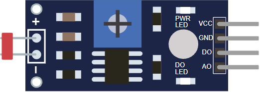
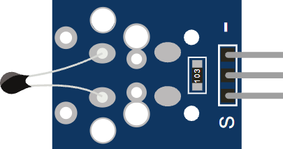
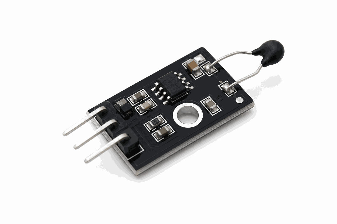
Before looking at the circuit, it helps to see the module first so the pin side and board shape are easier to recognize.
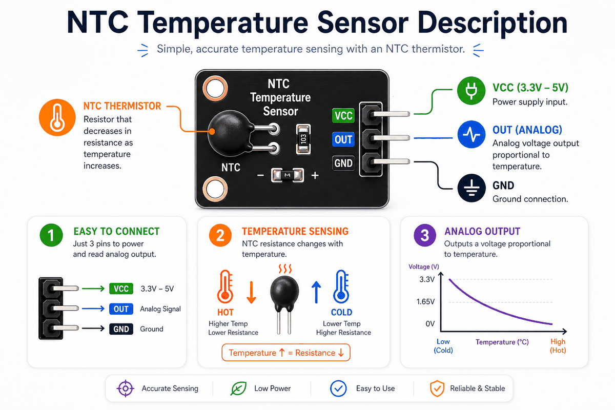
Description
An NTC sensor uses a thermistor whose resistance goes down when the temperature goes up. That means the module does not give a fixed output. Instead, the voltage at OUT changes as the sensor warms up or cools down.
For beginners, the useful idea is simple: temperature becomes an analog value that the Arduino can read and turn into a decision. That can mean a Celsius estimate, a fan trigger, or a warning when the sensor crosses a set point.
Features
Here are the main things to know about the NTC Temperature Sensor:
| Feature | What it means |
|---|---|
| Analog output | The Arduino reads a smooth voltage change instead of only HIGH or LOW. |
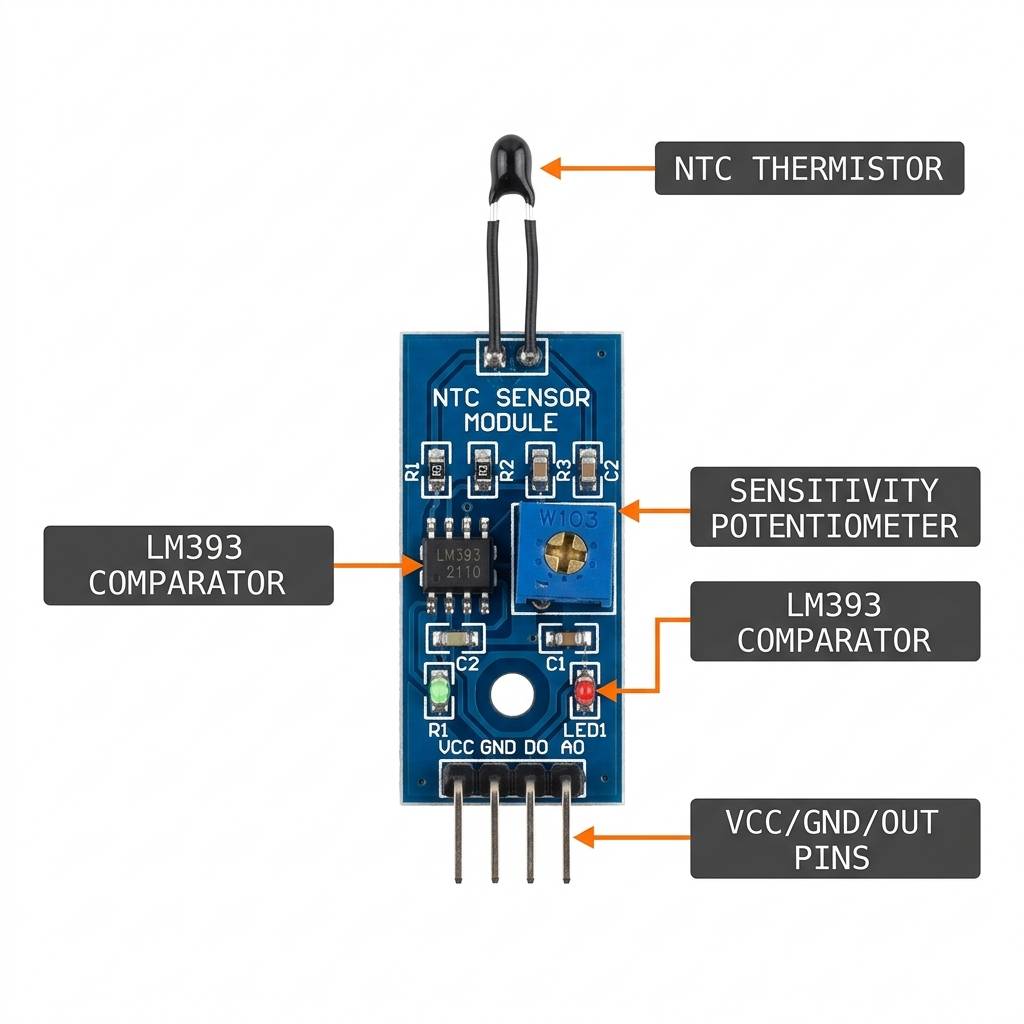
| NTC thermistor | Resistance drops as temperature rises, which is the core sensing behavior. |
| Voltage divider design | The module turns resistance change into a measurable signal. |
| Simple wiring | Usually needs VCC, GND, and OUT. |
| Calibration friendly | You can convert the raw reading into Celsius with a formula. |
| Good for control logic | Works well for fans, alarms, and threshold-based automation. |
The main advantage is the continuous reading. The sketch can react early when temperature starts drifting, instead of waiting for a hard threshold to trip.
NTC vs DS18B20 vs DHT
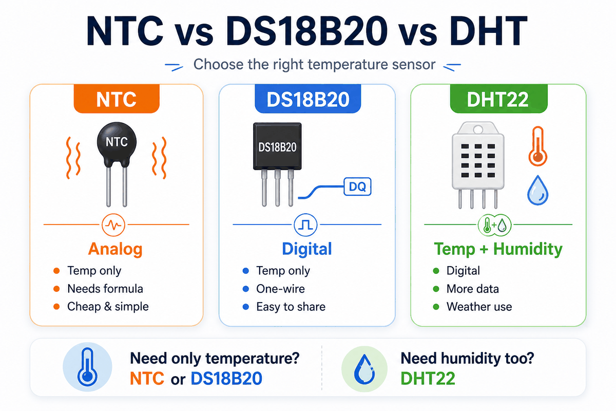
All three sensors can work in Arduino temperature projects, but they solve different problems.
| Sensor | Measures | Signal | Typical wiring | Best for |
|---|---|---|---|---|
NTC | Temperature only | Analog voltage from a resistor divider | VCC, GND, OUT | Simple temperature monitoring and fan control |
DS18B20 | Temperature only | Digital 1-wire | VCC, GND, DQ plus pull-up resistor | Clean digital temperature readings and multi-sensor setups |
DHT22 | Temperature and humidity | Digital timed protocol | VCC, DATA, NC, GND | Weather stations and room climate projects |
- Pick
NTCfor the easiest analog temperature reading. - Pick
DS18B20for digital temperature and easy multi-sensor wiring. - Pick
DHT22for temperature plus humidity in one module.
In short, NTC is the analog choice, DS18B20 is the digital choice, and DHT22 is the one to use when humidity matters too.
How Does It Work?
The sensor uses a thermistor and a resistor as a voltage divider. When temperature changes, the resistance changes, and the voltage on OUT moves with it.
The Arduino reads that voltage with analogRead(). The value is still raw, but it is enough for the sketch to estimate temperature or check a threshold.
Voltage Divider Behavior
The divider is the important part. When the thermistor gets warmer, its resistance drops, and the output voltage shifts. That change is what the Arduino measures.
Raw Reading To Temperature
Once the sketch has the raw analog value, it can convert that number into Celsius with the Beta formula or another calibration method. The exact math changes with the thermistor, but the workflow stays the same.
NTC Temperature Sensor Pinout
The module uses a small pin layout: power, ground, and one analog output. That keeps the wiring short and the code easy to follow.
| Pin | Meaning | Beginner note |
|---|---|---|
VCC | Power supply for the module | Usually connect to 5V on an Arduino Uno. |
GND | Ground reference | Must share ground with the Arduino. |
OUT | Analog temperature signal to the Arduino | Connect to an analog pin like A0. |
The sensor works through a voltage divider. The thermistor and fixed resistor turn temperature into a changing voltage, and the Arduino reads that voltage on OUT. If the divider is wired the wrong way, warmer temperatures can make the reading move backward.
- VCC powers the module.
- GND gives the circuit a shared reference.
- OUT sends the analog value to the Arduino.
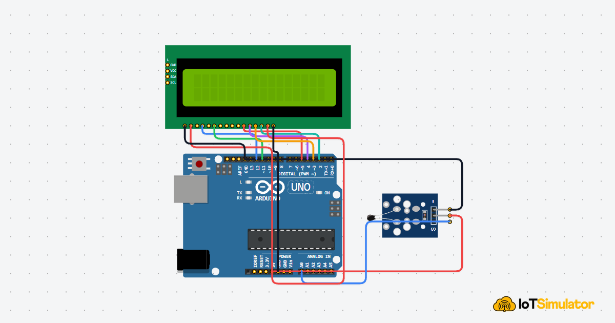
Arduino With NTC Temperature Sensor
This circuit preview shows an Arduino Uno connected to the NTC module. The setup only needs one analog input, so it is easy to test right away.

Pin Connection
The connection table below matches the circuit preview. The Arduino only needs one analog input, so the wiring stays short.
Provides power to the sensor module.
Shared ground reference for stable readings.
Feeds the analog temperature signal into Arduino.
Because this is an analog sensor, the reading changes gradually instead of jumping between two states. That makes it useful for smoothing, early fan control, and steady temperature display updates.
Arduino Code
This example reads the raw value from the sensor and converts it into Celsius using the Beta formula. It is a solid starting point for room monitors, fan controllers, and temperature alerts.
About analogRead()
The analogRead() function turns the physical voltage into a number the sketch can use. On an Arduino Uno, that number usually ranges from 0 to 1023, so the reading can be compared or converted without extra hardware.
The sketch prints a live temperature estimate every half second. In a real project, that value can switch a fan on, drive an LCD, or feed another part of the system.
How The Code Works, Part By Part
Let's break the sketch into smaller pieces so the flow is easier to understand and easier to change later.
Setup
The setup block starts Serial Monitor and prepares the sketch for temperature reading.
Read The Sensor
Next, the Arduino reads the analog voltage from OUT. This is the raw value that changes as the thermistor gets warmer or cooler.
Convert To Celsius
This part turns the raw analog reading into a temperature estimate. The formula uses the Beta coefficient, which is a common way to approximate an NTC thermistor curve.
Output And Repeat
Finally, the sketch prints the result and waits before reading again. That pause keeps the output easy to follow while still giving you a live update.
Wrapping Up
The NTC Temperature Sensor is a useful way to bring temperature into an Arduino project. Once you understand the voltage divider and the analog reading, it is easy to reuse in different builds.
It is a strong beginner sensor because it shows the full path from physical heat to a usable number in code.
A good next step is to pair it with a fan, a warning LED, or a display so the reading leads to a visible response.