Tutorial7 min read
analogRead vs digitalRead — When to Use Each One
Some sensors give you a simple yes or no. Others give you a number. Learn when to use digitalRead and when to use analogRead, and understand the difference between a switch and a sensor.
When I first started with Arduino, I connected a photoresistor to an analog pin and wrote
digitalRead() in my code. The Serial Monitor showed nothing but 0s and 1s that made no sense. I spent an hour checking wires before I realized the problem: I was using the wrong function. That is the moment every beginner faces.The difference between
digitalRead() and analogRead() is simple once you understand it, but getting it wrong means either missing half your data or overcomplicating a simple reading. digitalRead() checks whether a pin is above or below a voltage threshold and returns either HIGH or LOW. It is a one-bit measurement: on or off, yes or no. analogRead() measures the exact voltage on a pin and returns a number from 0 to 1023, giving you 1024 possible values.The Arduino Uno uses a 10-bit successive-approximation ADC that performs a binary search internally, comparing the input voltage against a reference to find the closest digital representation. It takes roughly 100 microseconds per sample, which works out to about 10,000 samples per second. The whole process is invisible to you — you call one function and get a number back — but knowing what happens inside helps you choose the right tool for each job.
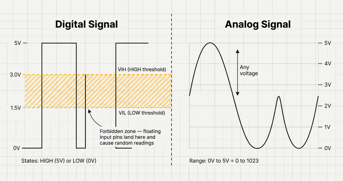
Digital vs analog signal comparison
The digital signal on the left has only two states. The analog signal on the right changes continuously. Your choice of function determines which world you see.
Quick Comparison
The table below shows how the two functions compare side by side. The biggest difference is resolution: digitalRead gives you one bit of information, while analogRead gives you ten bits. The time cost is also important — analogRead takes about 100 times longer than digitalRead. Keep these numbers in mind when deciding which function to use in your project.
| Feature | digitalRead() | analogRead() |
|---|---|---|
| Returns | HIGH or LOW (1 or 0) | 0 to 1023 |
| Resolution | 1 bit | 10 bits |
| Voltage per step | ~1.5V threshold (5V board) | ~4.88 mV per step (5V ref) |
| Time per reading | < 1 microsecond | ~100 microseconds |
| Samples per second | > 1,000,000 | ~10,000 |
| Pin type required | Any digital pin | Analog pin (A0-A5) |
| Circuit needed | Pull-up resistor often required | Voltage divider or direct sensor |
digitalRead — The Yes or No Function
The ATmega328P digital inputs use a Schmitt trigger circuit, which provides hysteresis to prevent noise from causing false readings. According to the datasheet, a voltage below approximately 0.3 times VCC is reliably read as LOW. A voltage above approximately 0.6 times VCC is reliably read as HIGH. Between these thresholds, the reading is undefined. This is the forbidden zone. If your input signal falls in this zone, the pin can randomly return HIGH or LOW depending on electrical noise, temperature, and other factors. The SparkFun logic level tutorial describes this as the floating state.
Here is when you should use digitalRead:
- Pushbuttons and switches — clean HIGH/LOW signals.
- PIR motion sensors — digital output that goes HIGH when motion is detected.
- Tilt switches — orientation detected as open or closed.
- Digital temperature sensors with alarm outputs.
- Any module with a digital output pin that goes to VCC or GND.
The digital inputs on the ATmega328P are also used for hardware interrupts on pins 2 and 3. When you need to detect a change in state immediately, you can attach an interrupt that triggers on RISING, FALLING, or CHANGE. For most beginner projects, polling with
digitalRead() in loop() is fast enough. But if your loop has delays or long-running operations, interrupts give you better responsiveness.A floating pin is like a microphone left on in a quiet room. It picks up everything — nearby wires, your hand movement, radio interference. A pull-up resistor is like putting that microphone in a soundproof box with a known background hum. The signal is predictable even when nothing is happening.
analogRead — The Measuring Function
The Arduino ADC uses a successive-approximation register architecture. According to Wikipedia, it performs a binary search. It starts by comparing the input voltage against half the reference voltage. If the input is higher, it keeps the top half and compares against three-quarters of the reference. If lower, it keeps the bottom half and compares against one-quarter. It repeats this for each of the 10 bits, which is why
analogRead() takes about 100 microseconds. The reference voltage defaults to the board operating voltage: 5V on the Uno, 3.3V on most ESP32 boards.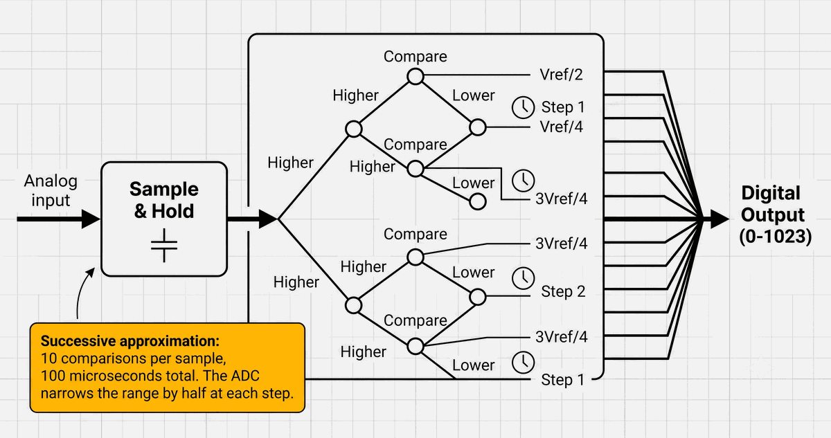
Arduino ADC internal architecture
Each comparison in the binary search cuts the voltage range in half. Ten comparisons later, the ADC has narrowed the reading to one of 1024 possible values and returns it to your sketch.
Each step in the 10-bit range represents approximately 4.88 millivolts at 5V reference or 3.22 millivolts at 3.3V. You can change the reference voltage using
analogReference(). The INTERNAL option on the Uno provides 1.1V, giving about 1.07 millivolts per step. This is useful when measuring small sensor voltages. For example, a TMP36 temperature sensor outputs 10 millivolts per degree Celsius. At 5V reference, room temperature gives a reading of about 240. Switching to the 1.1V internal reference increases the reading to nearly the full range, giving you much better resolution.Here is when you should use analogRead:
- Potentiometers — position sensing as a variable voltage.
- Joystick axes — X and Y position as analog values.
- Photoresistors — light level as a changing voltage.
- Analog temperature sensors like the TMP36.
- Gas sensors — concentration as a varying analog signal.
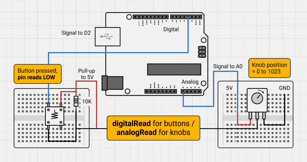
Button and potentiometer wiring diagram
A button needs only one resistor and a digital pin. A potentiometer uses two power connections and an analog pin. The wiring itself tells you which function to use.
A Practical Example: The Photoresistor
A photoresistor module often provides both an analog output and a digital output. The analog output voltage changes with the light level. The digital output goes HIGH or LOW depending on whether the light exceeds a threshold you set with an onboard potentiometer. This one module demonstrates the entire decision process.
If you only need to know whether a room is dark enough to turn on a light, the digital output with
digitalRead() is sufficient. If you need to measure the exact brightness for data logging or gradual dimming, the analog output with analogRead() gives you the full 10-bit resolution. The same module, two outputs, two completely different reading strategies.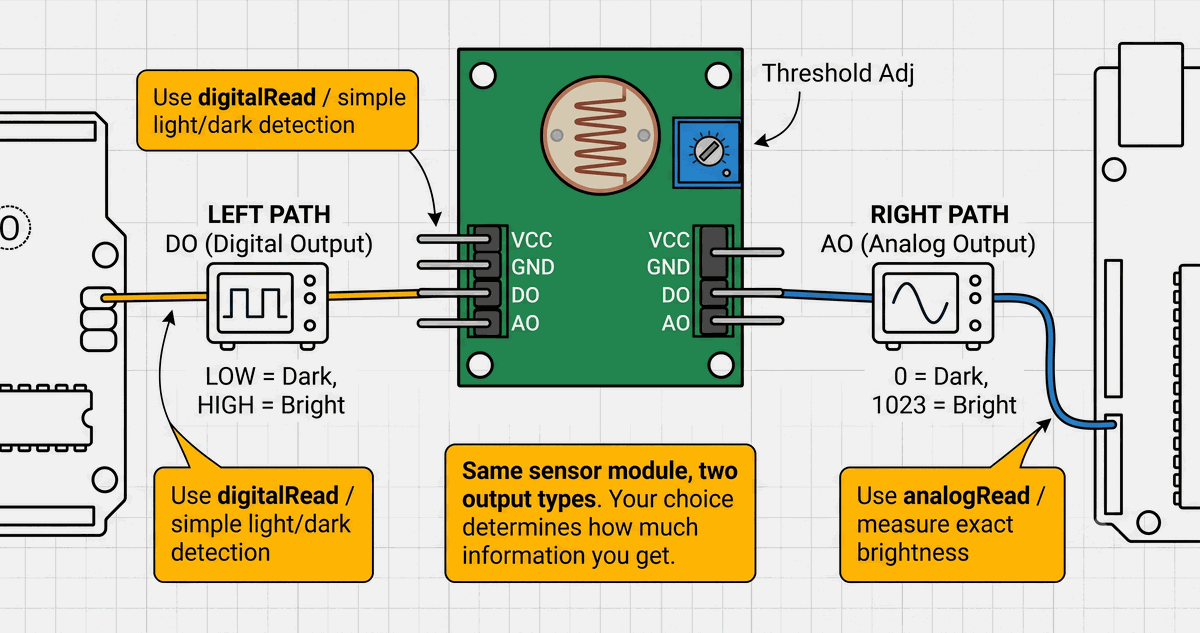
Photoresistor module with dual outputs
The same sensor feeds two paths. The digital path gives you a simple threshold. The analog path gives you the full picture. Which one fits your project depends on what you need to know.
The rule is simple: if the component has two states, use digitalRead. If it produces a range, use analogRead. When in doubt, check the datasheet or try both and see which gives you useful data.
Performance Comparison
digitalRead() is significantly faster than analogRead(). A single digitalRead() takes less than a microsecond because it simply reads a register value. analogRead() blocks for approximately 100 microseconds while the ADC performs its conversion. If your loop reads six analog sensors sequentially, the total delay is about 600 microseconds, which limits your loop rate to roughly 1,600 iterations per second.On the ESP32-C3 and other modern microcontrollers, the ADC is faster and can be configured for different resolutions and attenuation levels. But the fundamental tradeoff remains:
digitalRead() gives you speed with minimal information, and analogRead() gives you detailed information at the cost of speed.| Scenario | digitalRead() | analogRead() |
|---|---|---|
| Reading a button | Perfect — only two states exist | Overkill — wastes resolution and time |
| Reading a potentiometer | Useless — cannot detect position | Essential — 1024 positions |
| Reading a PIR sensor | Perfect — motion or no motion | Useless — sensor output is digital |
| Reading a photoresistor | Works if threshold is set | Better — full light range data |
Which One Should You Use?
If the component has two states — pressed or released, on or off, present or absent — use
digitalRead(). It is faster, simpler, and uses less code. If the component produces a range of values — a voltage that changes with light, temperature, pressure, or position — use analogRead() on an analog input pin. The extra resolution is worth the conversion time.Some components, like the photoresistor module, offer both outputs on the same board. In that case, your choice determines how much information you get from the sensor. The IoTSimulator supports both reading methods on all supported boards, so you can test both approaches side by side without changing any hardware.
Categories for this post
Tags
#analog #digital #beginner #arduino

About The Author
Muhammad Ichsanul FadhilI am a 21-year-old IoT enthusiast who loves microcontrollers and exploring new components. I built IoTSimulator to help beginners learn without needing a pile of hardware.