Deep Dive8 min read
What Is the Difference Between 3.3V and 5V Logic?
Plugging a 5V sensor into a 3.3V board can work, damage the board, or give wrong readings. Learn why logic levels matter and how to match them safely.
Few things in electronics are as annoying as a voltage mismatch. It is a silent problem. Your wiring looks perfect, your code compiles, and the power is on. Yet, your sensor either sends back garbled text or does not respond at all.
From my experience, I have spent hours tracing glitches only to find a voltage mismatch. If you connect a 5V board to a 3.3V board directly, it might work for a few hours. Then, the pin suddenly dies. This delayed failure makes it very hard to debug.
If you connect a 3.3V sensor to a 5V board, you get a different issue. It won't damage anything, but the 5V board might completely ignore the signal. The 3.3V signal is simply too low to register as 'on' or HIGH.
At its core, a 'logic level' is the voltage a chip uses to represent a 1 (HIGH) or a 0 (LOW). Different boards use different voltages. If they disagree on the rules, you get wrong readings or dead chips.
To visualize how these voltage thresholds compare and identify where the danger zones lie, look at the comparison diagram below:
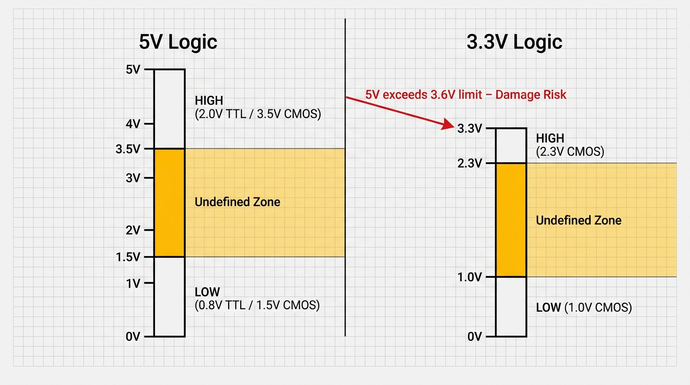
Figure 1: Side-by-side comparison of 5V and 3.3V CMOS/TTL input thresholds, highlighting the undefined danger zones.
A digital signal is never just a simple 'on' or 'off.' Every integrated circuit follows its own rules for interpreting logic states. When two components in your design disagree on these rules, you risk data corruption, system instability, or permanent hardware damage.
| Logic Standard | Low State (LOW) | High State (HIGH) | Undefined Zone |
|---|---|---|---|
| 5V CMOS (typical) | < 1.5V (30% VCC) | > 3.5V (70% VCC) | 1.5V to 3.5V |
| 5V TTL (fixed) | < 0.8V | > 2.0V | 0.8V to 2.0V |
| Arduino Uno (ATmega328P) | < 1.5V | > 3.0V | 1.5V to 3.0V |
| 3.3V CMOS (typical) | < 1.0V (30% VCC) | > 2.3V (70% VCC) | 1.0V to 2.3V |
5V Boards: Arduino Uno, Mega, Nano
The classic Arduino Uno runs on 5V. It sees any signal below 1.5V as LOW, and anything above 3.0V as HIGH. The space between 1.5V and 3.0V is a dead zone. If a signal floats around 2.2V, the Arduino gets confused, leading to random bugs.
A helpful logic levels guide by SparkFun notes that the Arduino family features a wider safety margin compared to traditional TTL chips. This design choice makes the platform far more tolerant of noisy, imperfect signals. Nevertheless, keeping your lines clean is always the best practice.
When set as an output, an Arduino pin sends out a full 5V for HIGH and 0V for LOW. This is perfect for other 5V devices. Each pin can output up to 40 milliamps. That is enough for an LED, but not enough to run a motor directly.
I learned this the hard way when I plugged a small motor straight into an Arduino pin. The pin died instantly. While the rest of the board worked fine, that pin was gone forever.
The 5V standard is very common. Boards like the Arduino Uno, Mega, and Nano all use it. Most classic modules—like the HC-SR04 distance sensor and DHT11 temperature sensor—run at 5V too. This makes them easy to plug in and use.
To compare how these classic 5V boards stack up against modern, low-power 3.3V boards, take a look at the comparison of logic boards below:
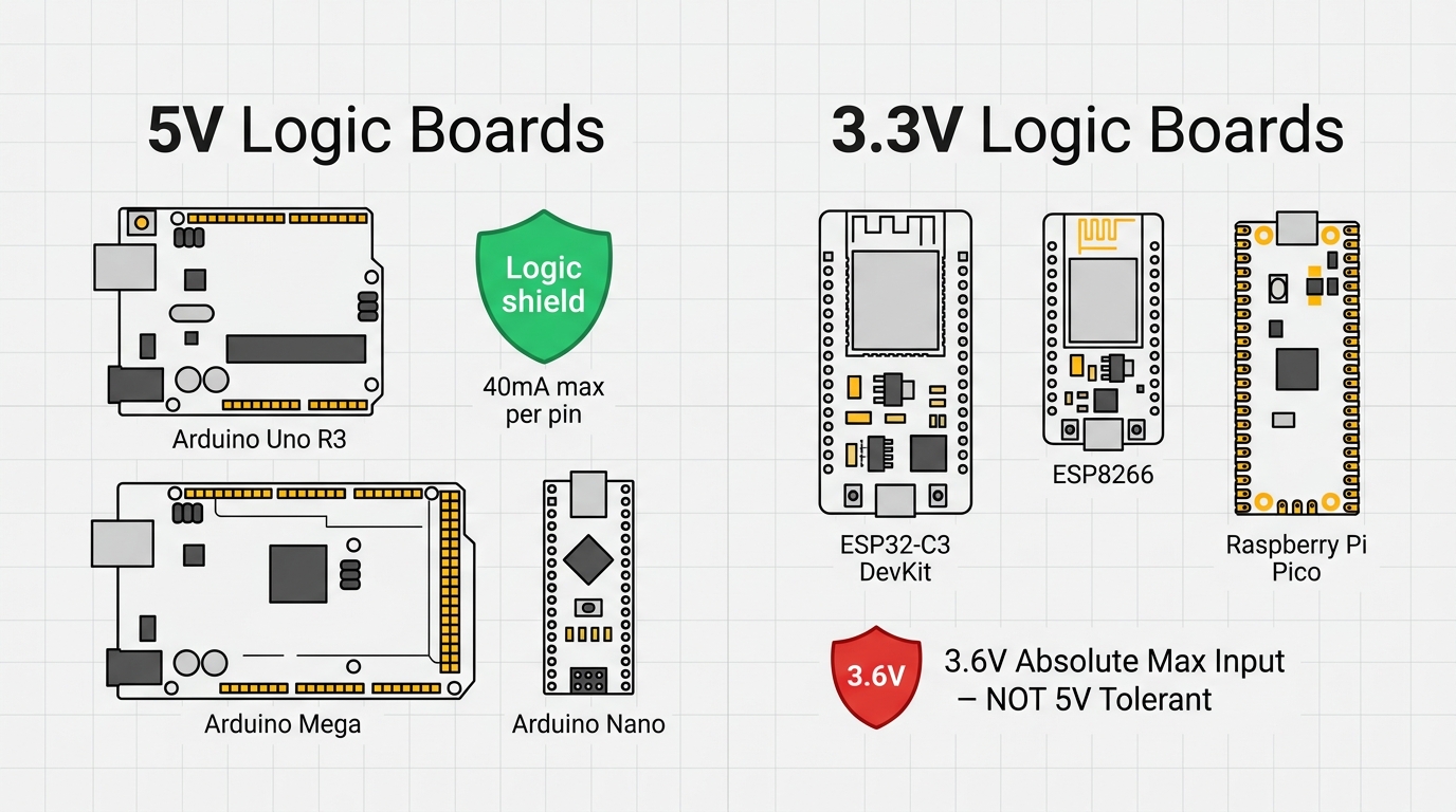
Figure 2: Microcontrollers grouped by their logic level, highlighting the strict overvoltage limitations of modern 3.3V chips.
3.3V Boards: ESP32, ESP32-C3, Raspberry Pi Pico
Modern chips use smaller internal parts that cannot handle 5V. To prevent damage, they run on 3.3V. Microcontrollers like the ESP32, ESP32-C3, and Raspberry Pi Pico use this standard.
Sending 5V into a 3.3V pin will quickly destroy the chip. The safe limit is usually around 3.6V. Anything higher will cause permanent damage.
A 3.3V chip outputs around 2.4V for a HIGH signal. This is usually enough for a 5V board to recognize it. However, sending a 5V signal into a 3.3V pin is dangerous because the voltage is too high.
Never assume a board is safe with 5V signals unless the datasheet explicitly says so. The ESP32-C3, for example, has no 5V-tolerant pins. Always protect these pins when connecting 5V parts.
Level Shifting Solutions
If you are sending signals one way—from a 5V output to a 3.3V input—a simple voltage divider is the easiest fix. By using two resistors in series (like a 1k and a 2k resistor), you can safely scale the 5V signal down to 3.3V.
The math is simple:
\[V_{out} = V_{in} \times \frac{R_2}{R_1 + R_2}\]With 1k and 2k resistors, a 5V input becomes 3.3V. I use this trick all the time for simple one-way connections.
However, a voltage divider does not work for two-way communication. If the 3.3V device needs to talk back, the resistors block the signal. For bidirectional lines like I2C, you need an active level shifter.
A common solution is a small level shifter module using a transistor. These are cheap and translate signals both ways automatically. Dedicated chips like the 8-channel TXS0108E are perfect for fast communication. I always keep a few of these modules on my desk.
To help you visualize both of these approaches, let's look at the circuit designs side-by-side:
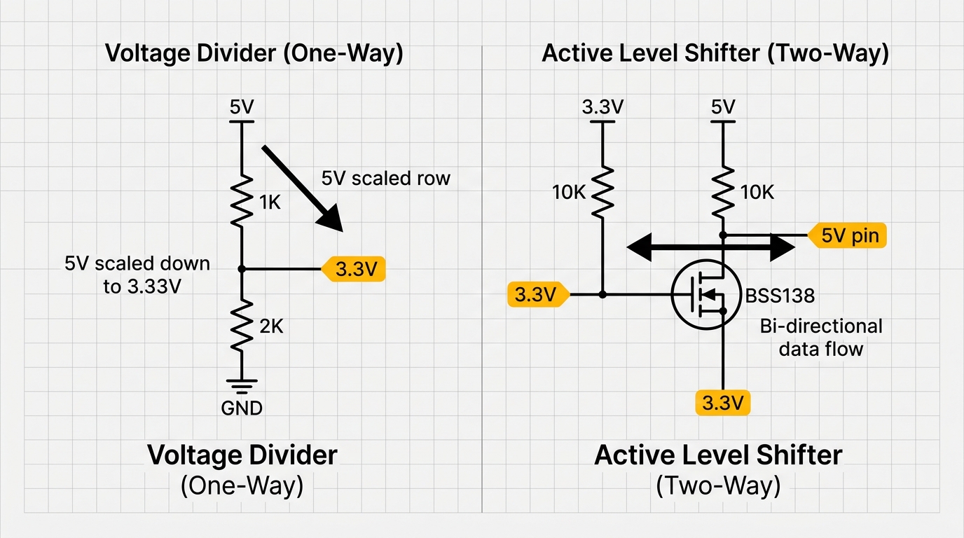
Figure 3: Comparing a simple passive voltage divider (unidirectional) with an active MOSFET-based level shifter (bidirectional).
Common Mistakes
The most common mistake is assuming all 3.3V pins can handle 5V. They cannot. Unless the datasheet says a pin is 5V-tolerant, assume it will burn out.
Another mistake is using a voltage divider on bidirectional data lines. This will scramble the data. Always use a proper level shifter module instead.
A third mistake is using the wrong voltage for pull-up resistors. If you pull an I2C line up to 5V, it can damage a 3.3V sensor. Always tie pull-up resistors to the lower voltage rail (3.3V).
To see the difference between a direct, risky setup and a safe one using a level shifter, look at these two hookups side by side:
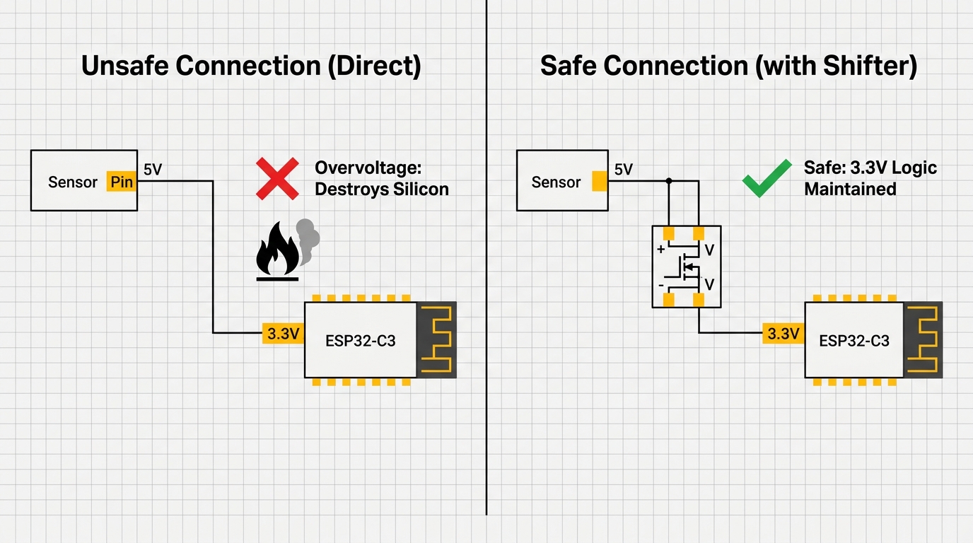
Figure 4: The direct connection puts modern microcontrollers at risk, whereas the active level shifter isolates and protects the pins.
How to Check Compatibility
Before wiring two devices together, you can verify their compatibility by looking up four key specifications in their datasheets. These parameters are typically located in the 'DC Characteristics' or 'Electrical Specifications' tables. They define the boundaries of the digital signals:
- VOH (Minimum Output High Voltage): The absolute lowest voltage the output pin will supply when transmitting a logic 1.
- VOL (Maximum Output Low Voltage): The absolute highest voltage the output pin will supply when transmitting a logic 0.
- VIH (Minimum Input High Voltage): The lowest voltage threshold the input pin requires to reliably register a logic 1.
- VIL (Maximum Input Low Voltage): The highest voltage threshold the input pin can receive and still reliably register a logic 0.
For direct communication to work, VOH must be greater than VIH, and VOL must be less than VIL. This quick check has saved me from damaging boards multiple times.
For example, a 3.3V board's VOH is around 2.4V. Since a 5V TTL input's VIH is 2.0V, the 3.3V signal registers as HIGH. However, a 5V output exceeds the 3.6V maximum rating of most 3.3V chips. That is why you need a level shifter when sending 5V to a 3.3V input.
Categories for this post
Tags
#voltage #logic-level #beginner #arduino #esp32

About The Author
Muhammad Ichsanul FadhilI am a 21-year-old IoT enthusiast who loves microcontrollers and exploring new components. I built IoTSimulator to help beginners learn without needing a pile of hardware.
Related Articles
Continue reading