Tutorial5 min read
Building Your First Circuit Without a Breadboard
You can build a working Arduino circuit without a breadboard using direct pin connections, twisted leads, or the simulator canvas. Learn when you need a breadboard and when you can skip it.
Most people think building circuits requires a breadboard full of jumpers. That is not always true. If your circuit has only a couple of parts, you can connect them directly to the Arduino pins.
An LED with a resistor between pin 13 and GND does not need a breadboard. The resistor lead goes into the header, and the LED connects to the resistor. It works exactly the same way, with fewer parts and less mess.
The word "breadboard" comes from the early days of radio. Hobbyists nailed copper wires and terminal strips to literal wooden bread cutting boards.
According to Wikipedia, the first solderless breadboard was patented in 1971 by Ronald Portugal of E&L Instruments. It used holes spaced 0.1 inches apart — the same spacing as DIP integrated circuits — with spring clip contacts underneath. The spring clips are tin-plated phosphor bronze, rated for 1 ampere at 5 volts or 0.333 amperes at 15 volts.
That basic design has not changed much in over fifty years. What we now call a breadboard is a relatively recent invention, and people built working circuits for decades without one. Understanding that history makes it easier to see the breadboard for what it is: a convenience, not a requirement.
When You Do Not Need a Breadboard
The simplest Arduino circuit is an LED on pin 13. The Uno has a built-in resistor on that pin, so you can connect an LED directly between pin 13 and GND. No extra parts needed.
For other pins, use an external resistor. A 220-ohm resistor between the pin and the LED anode, with the cathode to ground, creates a complete circuit inside the headers. No breadboard. No jumper wires. No soldering.
I have done this many times when I just needed to verify a pin was working. It takes seconds and saves the trouble of setting up a breadboard for a single LED.
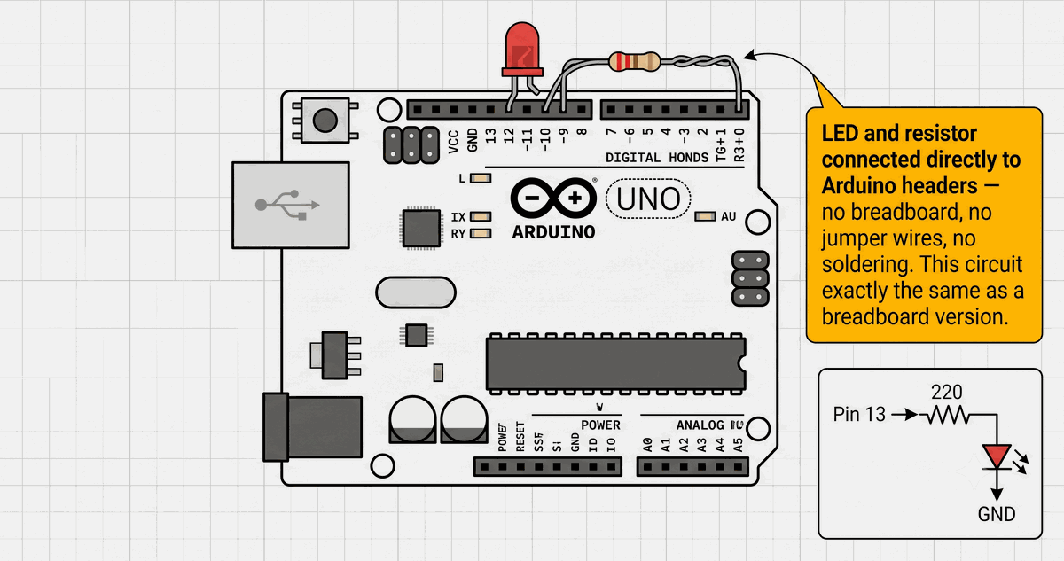
LED and resistor connected directly to Arduino pin headers
You can also twist leads together. Twist the resistor leg with the LED anode leg, insert the resistor into the Arduino pin, and connect the LED cathode to GND. This is called point-to-point construction. It was standard practice before breadboards existed. The connection is temporary and easy to undo with pliers. Keep the twisted section short so exposed metal does not touch anything else.
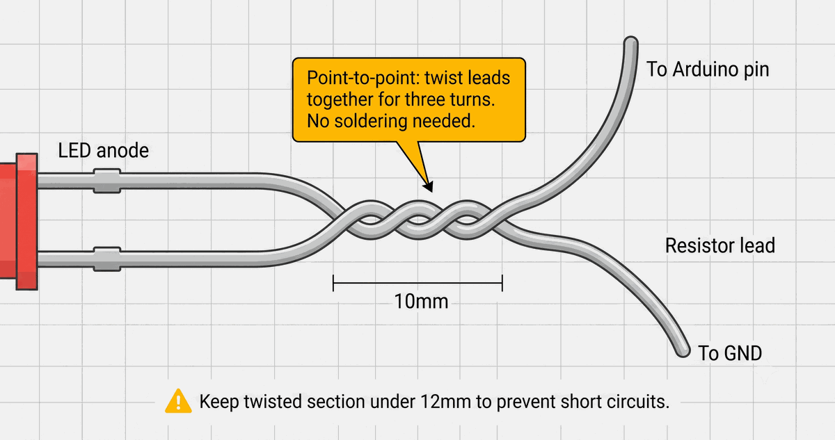
Twisted lead connection
What a Breadboard Actually Does
A breadboard gives you a grid of pre-connected holes. Five holes in each row connect underneath through a spring clip. The long rails on the sides distribute power and ground — red for VCC, blue or black for GND. The center gap lets DIP chips straddle both halves so each pin gets its own row of five holes.
According to Wikipedia, a full-size breadboard has 56 to 65 rows per strip, giving 784 to 910 tie points. But breadboards are not perfect. Parasitic capacitance and contact resistance limit them to circuits under about 10 MHz. Spring clips wear out over time. Loose connections cause intermittent problems that are hard to find.
Connecting components directly to the Arduino pins eliminates those failure points entirely. That makes direct wiring more reliable for simple circuits, even if it looks less polished.
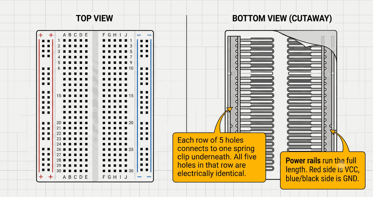
Breadboard internal spring clip structure
But direct connections have limits. The moment you have more than two components sharing one node, knowing which holes connect to which on a breadboard stops being optional and starts being the difference between a working circuit and a confusing mess.
If your circuit needs more than two connections to the same point, a breadboard becomes useful. A button with a pull-up resistor needs three connections: the button, the resistor, and the Arduino pin. On a breadboard, they share one row. Without one, you would need to twist leads together or use a terminal block.
The comparison below shows the same circuit built both ways. It helps to see how the wiring changes while the circuit stays exactly the same.
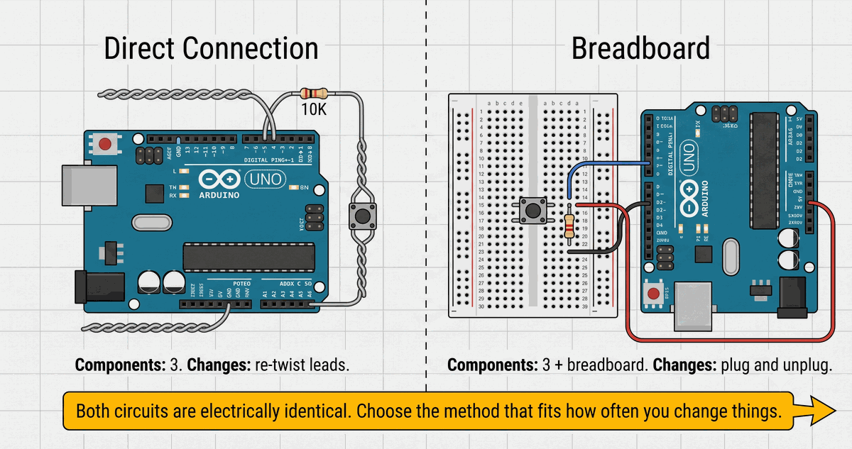
Direct connection vs breadboard comparison
Alternatives to Breadboards
When your circuit outgrows direct connections but does not need a custom PCB, several options exist.
- Stripboard (Veroboard). Parallel copper strips you cut to make isolated pads. Connections are soldered and permanent. The 0.1-inch pitch matches standard breadboard spacing.
- Perfboard. Individual pads with no pre-connected strips. Full control over routing, but more wiring needed.
- Dead-bug construction. A chip glued upside down with legs in the air, soldered directly to a copper ground plane. Common for high-frequency circuits where breadboard capacitance causes problems.
- Wire wrapping. A tool wraps 30 AWG wire around square posts to create gas-tight connections without soldering. Was standard in professional prototyping.
When to Use the Simulator
The IoTSimulator lets you build circuits without any physical parts. The canvas replaces the breadboard. Virtual wires replace jumper cables. Add components from the palette, connect them on screen, and run your code. No loose wires, no shorts, no damaged components.
I use the simulator whenever I want to test an idea before deciding whether to build it physically. If the circuit works in the simulator, I know the exact pins and resistor values to use. The physical build becomes a wiring exercise instead of a debugging session.
Recommended Approach for Beginners
Start without a breadboard. Connect an LED with a resistor directly to the Arduino. Once that works, add a button with a pull-up resistor. You now have three components sharing connections. That is where a breadboard starts making sense.
Add a small breadboard and move the components onto it. You will see why breadboards are everywhere — they make adding and removing parts easy.
After a few builds, you will know when to use direct connections and when to reach for the breadboard. I still connect things directly for quick tests, but I grab the breadboard as soon as the circuit has more than two components sharing one node.
Categories for this post
Tags
#beginner #wiring #arduino

About The Author
Muhammad Ichsanul FadhilI am a 21-year-old IoT enthusiast who loves microcontrollers and exploring new components. I built IoTSimulator to help beginners learn without needing a pile of hardware.