Tutorial7 min read
How to Use a Breadboard — Rows, Columns, and Common Mistakes
A breadboard lets you build circuits without soldering. Learn how the internal rows and power rails are connected, and avoid the most common mistakes beginners make.
A breadboard lets you build circuits without soldering, but only if you understand how the holes are connected underneath. The plastic block hides a grid of metal spring clips that link certain holes together. Put a component leg into the wrong row and your circuit will not work, even though the wiring looks correct.
I have seen beginners spend an hour debugging a circuit that was perfectly wired — except one leg was in the wrong row. Understanding the internal layout is the difference between a circuit that works on the first try and one that causes frustration.
The holes are spaced 0.1 inches apart, matching the pin spacing of DIP integrated circuits. Under each row, a tin-plated phosphor bronze spring clip links the five holes together, rated for about 1 ampere at 5 volts — plenty for Arduino projects. The modern solderless breadboard design was patented in 1971 by Ronald Portugal of E&L Instruments, and the layout has not changed much since.
Breadboard Sizes and Types
Breadboards come in several standard sizes. The most common is the half-size breadboard with approximately 400 tie points, split into two sections of 30 rows each. Full-size breadboards have around 830 tie points with 63 rows. Mini breadboards with 170 tie points are useful for small circuits with only a few components. The tie point count refers to the total number of holes available for inserting components and wires.
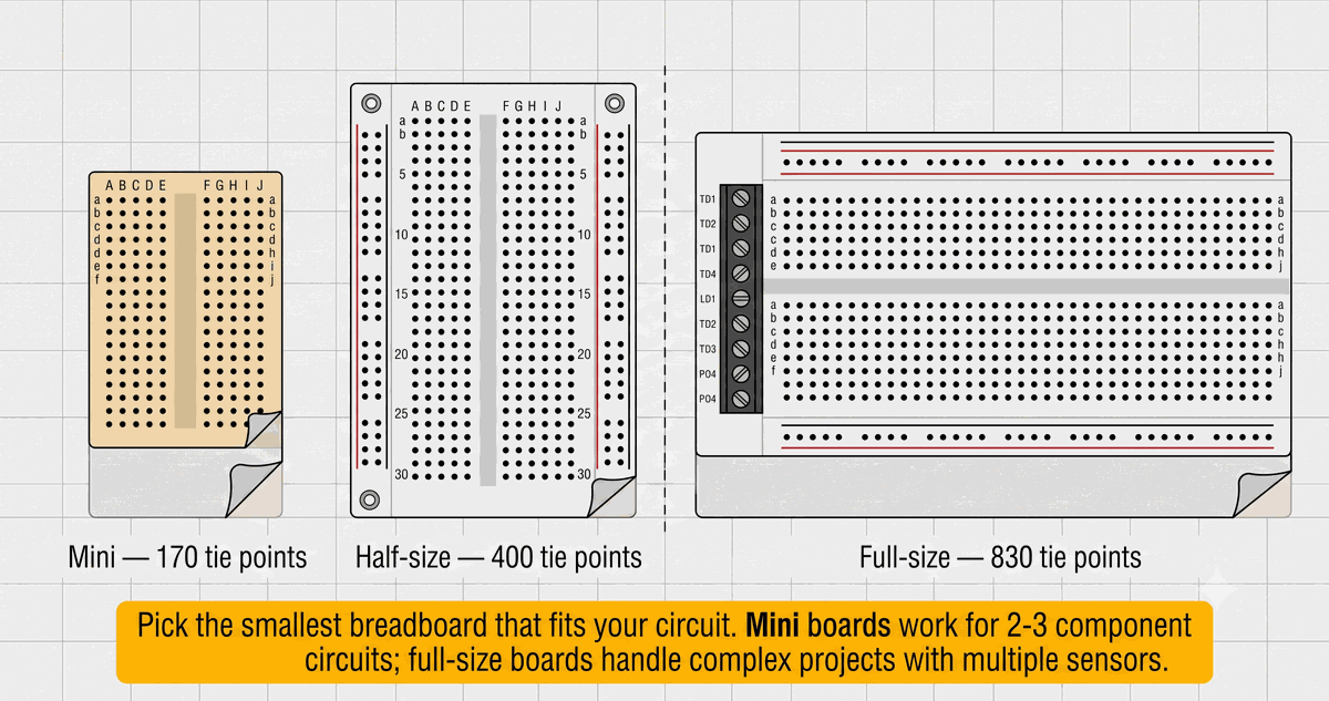
Mini, half-size, and full-size breadboards compared side by side
This is how the three common sizes look next to each other. I usually grab a half-size board for most Arduino experiments — it fits an Uno, a sensor module, and a handful of jumper wires with room to spare.
Some breadboards have a self-adhesive backing with a peel-off paper strip. This lets you mount the breadboard onto a flat surface or inside an enclosure. Others have metal mounting holes at the corners for screw attachment. The adhesive backing is convenient for temporary setups, but once it gets dusty, it loses its grip. I prefer using breadboards with metal mounting holes for projects that I plan to keep assembled for a while.
The plastic used in most breadboards is ABS, which is durable and resistant to melting from soldering iron heat. However, it can melt if you hold a soldering iron against it for too long. If you decide to solder wires directly to a breadboard pin, keep the iron contact under two seconds.
There is one thing to keep in mind with budget breadboards: the spring clips are not always reliable. Some cheap boards have clips that do not grip properly or are missing altogether. If a connection seems dead, try moving the component to a different row. The IoTSimulator breadboard follows the standard layout with quality clips so you can practice without wondering whether the hardware is at fault.
Power Rails
The long rows along the top and bottom edges are the power rails. They are marked with red and blue lines, or plus and minus symbols. The red rail is typically used for the positive supply, such as 5V or 3.3V. The blue or black rail is used for ground.
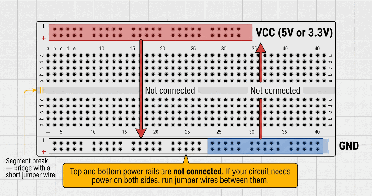
Breadboard power rail layout with VCC and GND markings
See how the rails run the full length of the board. One detail that catches many beginners: the top power rail is not connected to the bottom rail. If your circuit needs power on both halves of the breadboard, you must run jumper wires from top to bottom.
Some breadboards also segment the power rails every 25 holes or so. Look for a gap in the colored marking on the side — that is where the metal strip inside is interrupted. If you need power across a break, bridge it with a short jumper wire. From my experience, this is one of those details that causes head-scratching moments when power reaches part of the board but not the rest.
Component Rows
The main area is split into two halves by a center notch. Each half has numbered rows, typically 1 through 30 on a half-size board or 1 through 63 on a full-size board. Each row has five holes labeled A through E on the left side and F through J on the right. All five holes in the same row are connected underneath by a single spring clip.
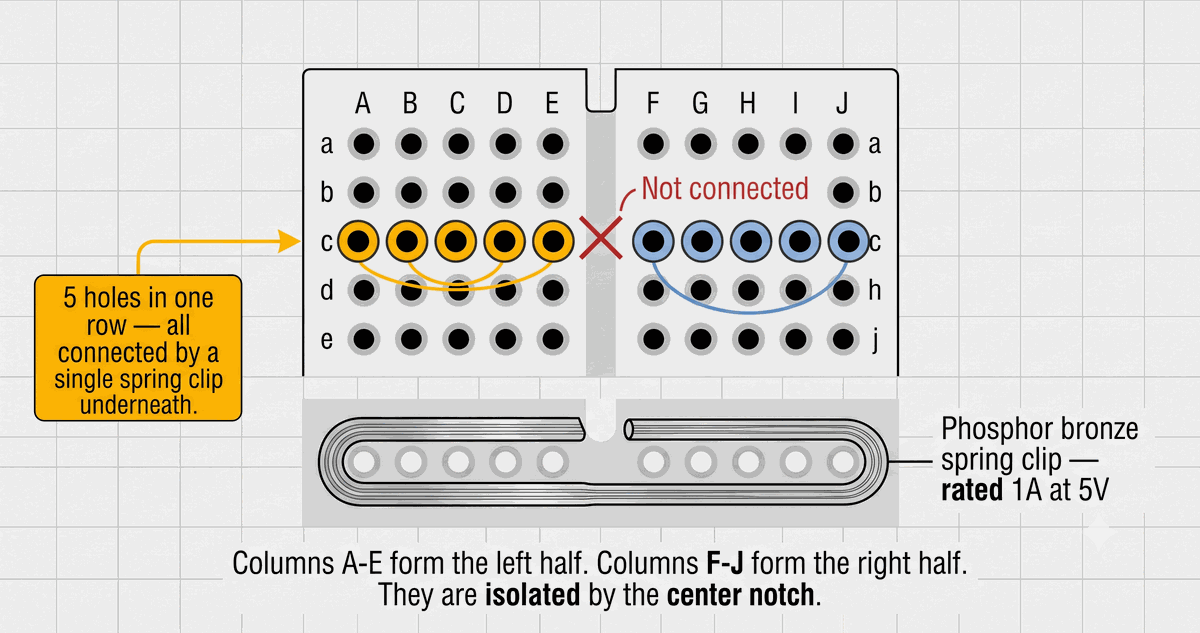
Breadboard row connection diagram showing five holes per row
The highlighted row shows exactly which holes share a connection. This means a component inserted into hole A1 is connected to B1, C1, D1, and E1 automatically. You do not need wires to connect points in the same row — just insert two leads into the same row and they are joined. It sounds obvious, but when you are focused on the schematic it is easy to accidentally insert two unrelated legs into the same row, shorting them together. If that happens, just move one leg to an empty row.
The five holes on the right side of the notch (F through J) are separate from the left side. Row 1E and Row 1F are not connected. This is why DIP chips straddle the center notch. The chip pins on the left go into column E and the pins on the right go into column F, keeping them isolated.
The Center Gap
The center gap runs the full length of the breadboard. Its main purpose is to allow DIP integrated circuits to fit without shorting their pins together. A DIP-8 chip has four pins on each side. The chip straddles the gap so the left pins go into column E and the right pins go into column F. Each pin then has its own row of five holes available for wiring. Without the center gap, the left and right pins would be in the same row and would short together.
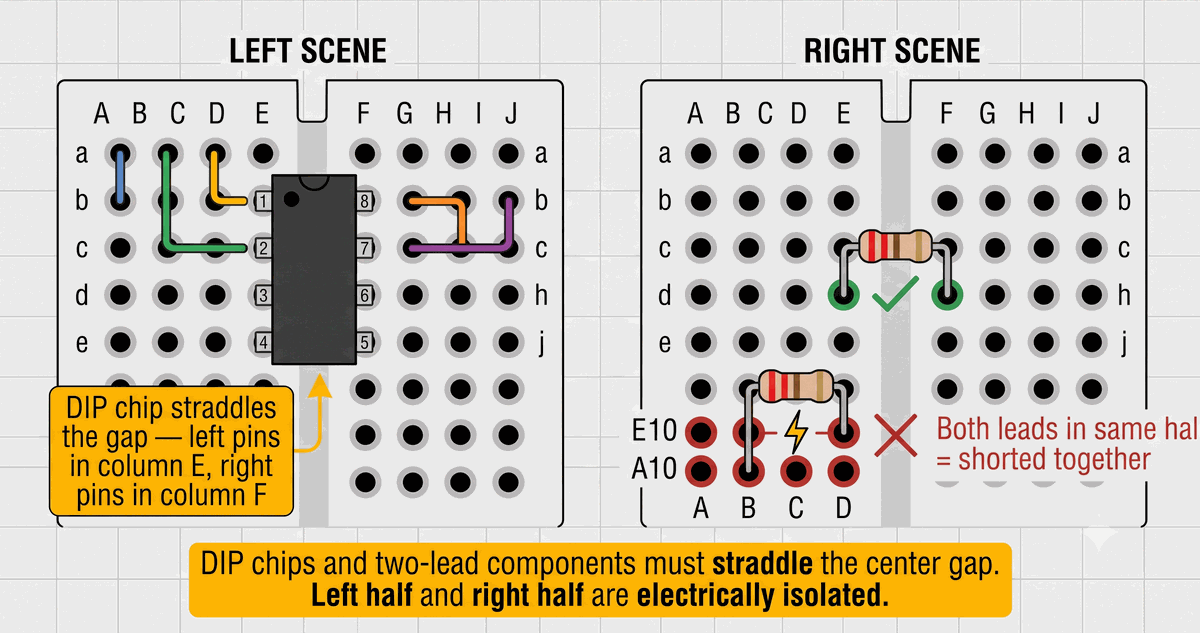
DIP chip and two-lead component correctly straddling the center gap
The image shows both a DIP chip and a two-lead component straddling the notch. The same principle applies to any resistor or LED — if the leads need to go into separate rows, make sure one lead goes into column A through E and the other into column F through J. Putting both leads in the same half shorts them together. I have done this myself more times than I care to admit.
The gap also makes it easy to identify rows visually. The left half uses columns A through E, and the right half uses F through J. When you build a circuit from a schematic, find the row number for each pin and use the five holes in that row for your connections. A full-size breadboard with 63 rows on each side gives you up to 630 connection points in the main area, plus the power rails.
Most breadboards also have a shallow channel running down the center gap on the underside. This channel allows you to cut the adhesive backing paper along the center line if you only need half a breadboard for a small project. You can snap or cut most breadboards along this channel to split them into two separate mini boards, though the plastic may not break evenly every time.
Choosing the Right Wire Gauge
Breadboard spring clips are designed for solid-core wire of 22 AWG (American Wire Gauge), which is approximately 0.64 millimeters in diameter. Stranded wire does not work well because the individual strands can bend and break inside the clip, leading to intermittent connections. If you only have stranded wire, twist the strands tightly or tin them with solder before inserting.
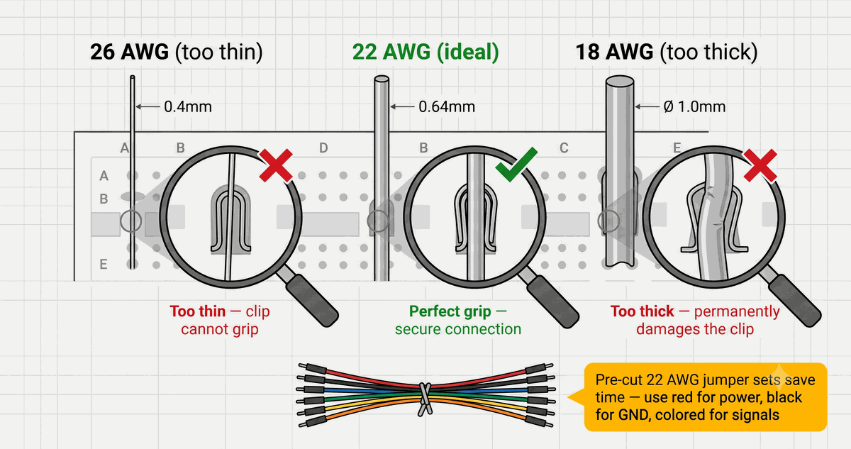
Wire gauge comparison showing 26 AWG, 22 AWG, and 18 AWG in breadboard holes
This is what the wrong and right wire gauges look like inside a breadboard hole. Wire that is too thin, such as 26 AWG or thinner, will not make reliable contact with the spring clips. The clip may not grip the wire firmly, causing it to fall out or lose contact when the board is moved. Wire that is too thick, such as 18 AWG, can damage the spring clip by spreading it open permanently. Once a clip is stretched, it will not grip any wire reliably.
Use 22 AWG solid wire for best results. Pre-cut jumper wire sets in various lengths and colors are inexpensive and save the trouble of stripping and cutting your own. Stick to a simple color convention: red for power, black for ground, and other colors for signal wires. Long jumper wires create a tangled mess that is hard to debug. Cut or select wires just long enough to reach their destination. A tidy breadboard is much easier to troubleshoot when something goes wrong.
Categories for this post
Tags
#breadboard #beginner #wiring #arduino

About The Author
Muhammad Ichsanul FadhilI am a 21-year-old IoT enthusiast who loves microcontrollers and exploring new components. I built IoTSimulator to help beginners learn without needing a pile of hardware.