Tutorial8 min read
How to Choose the Right Resistor for Any LED
Every LED needs a current-limiting resistor to prevent damage. Learn how to calculate the right resistor value using Ohm's Law, and find common values for red, green, blue, and white LEDs.

From my experience, one of the first mistakes beginners make is connecting an LED directly to a power source like an Arduino pin. Doing this will cause the LED to flash brightly for a split second before burning out forever. The reason is simple: LEDs have almost no internal resistance. A standard 5mm red LED, for instance, has a forward voltage of about 1.8 volts. If you hook it directly to a 5V supply, the circuit has a leftover 3.2 volts with nothing to block the flow of current.
The LED will try to draw as much current as the power pin can physically output. While an Arduino Uno pin can supply up to 40 milliamps, standard small LEDs are rated for a maximum of 20 milliamps. Without a resistor to limit this current, the excess flow creates an overcurrent condition that melts the delicate internal junction of the LED within seconds.
Ohm's Law Made Simple
According to Wikipedia, Georg Ohm published his famous law relating voltage, current, and resistance in 1827. The fundamental formula is V equals I times R, where V is the voltage in volts, I is the current in amperes, and R is the resistance in ohms. To calculate the exact resistor you need for an LED, we rearrange this formula. The equation becomes: R equals supply voltage minus forward voltage, divided by the target current.
Here is a quick breakdown of what these variables mean in a real circuit:
- Supply Voltage (V_supply): The voltage output by your controller. For example, it is about 5V on an Arduino Uno, or 3.3V on an ESP32-C3.
- Forward Voltage (V_forward): The voltage the LED consumes to light up. This value changes depending on the color of the LED and is listed in the component's datasheet.
- Target Current (I_current): The safe current limit for your LED. For standard indicator LEDs, the target is usually 20 milliamps, which converts to 0.02 amps in our equation.
To see how Ohm's Law coordinates these values in a basic LED circuit, check out this schematic layout:
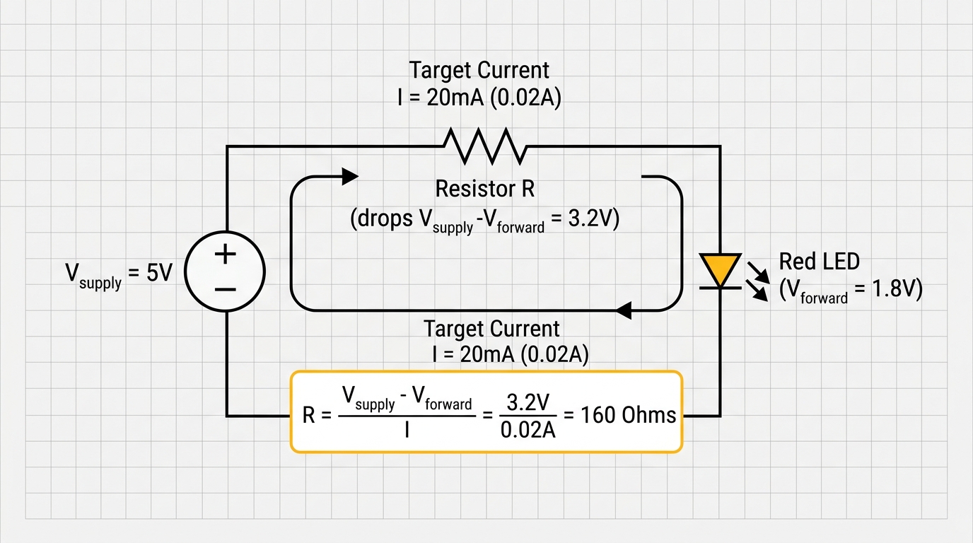
Figure 1: Visualizing how Ohm's Law calculates the resistor value based on supply voltage and LED forward voltage drops.
Calculating the Resistor Value
Let's trace how this math works for a red LED connected to a 5V Arduino pin:
- Find the voltage across the resistor: subtract the LED forward voltage (1.8V) from the supply voltage (5V) to get 3.2V.
- Divide this voltage by your target current (0.02A) to get the required resistance: 3.2 / 0.02 = 160 ohms.
- Choose a standard resistor value. Resistors are sold in standard value groups based on the E-series standards.
The closest standard value above 160 ohms in the common E12 series is 180 ohms or 220 ohms. If you choose a 220-ohm resistor, the actual current drops to about 14.5 milliamps. I've found that this is still plenty bright for an indicator LED, and it runs much cooler. In fact, a 220-ohm resistor is my favorite go-to choice for almost any basic indicator LED on a 5V board because it keeps the current safe for red, green, blue, and white LEDs alike.
If you are using a 3.3V microcontroller like the ESP32-C3, the calculation shifts:
- Calculate the resistor voltage: 3.3V minus the red LED's 1.8V forward voltage leaves 1.5V across the resistor.
- Find the resistance: 1.5V divided by the 0.02A target gives 75 ohms.
- Find the nearest standard resistor, which is 100 ohms. This resistor value limits the current to a safe 15 milliamps.
For green, blue, or white LEDs, the forward voltage is higher, typically around 3.0V. When running on a 3.3V supply, the voltage across the resistor is tiny: 3.3V minus 3.0V leaves only 0.3V. Using a standard 100-ohm resistor here yields a current of just 3 milliamps. While that sounds extremely low, modern high-efficiency LEDs are so bright that 3 milliamps is often enough for a clear indicator light.
LED Forward Voltages by Color
According to Wikipedia, the forward voltage of an LED depends on the semiconductor materials used to create it, which also dictates the light color. Different colors require different voltage levels to illuminate.
| LED Color | Forward Voltage Range (Vf) |
|---|---|
| Infrared | ~1.2V |
| Red | 1.7V to 2.0V |
| Yellow / Orange | 2.0V to 2.2V |
| Green | 2.8V to 3.2V |
| Blue / White | 3.0V to 3.4V |
You can compare the typical forward voltages for different LED colors on the scale below:
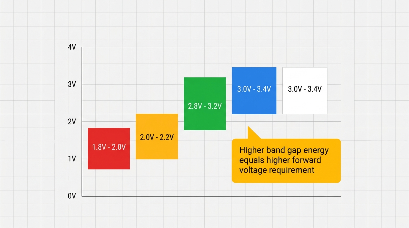
Figure 2: Comparing typical forward voltages across different LED wavelengths and colors.
One thing I noticed when testing LEDs is that the forward voltage drops slightly as the LED gets warm. If you run an LED without a current-limiting resistor, this temperature drop creates a dangerous loop called thermal runaway. As the LED heats up, its forward voltage decreases. This drop allows even more current to flow, which heats the LED further. The loop repeats until the LED overheats and burns out completely.
Common Resistor Values for Arduino
For quick prototyping, I recommend keeping these standard resistor values handy:
- For 5V Boards (like Arduino Uno): Use 220 ohms for red LEDs, and 100 ohms for green, blue, or white LEDs.
- For 3.3V Boards (like ESP32): Use 100 ohms for red LEDs, and 47 ohms for green, blue, or white LEDs.
These general-purpose values keep the current comfortably below the maximum 20 milliamp rating. This protects your components while keeping them bright enough for indicator panels. If you find the light is too bright for comfort, you can always swap in a higher resistor value. If it is too dim, you can lower the resistance, but you should never go below the calculated minimum value to protect your components.
Series and Parallel Wiring
If your design requires multiple LEDs, you can choose between two main wiring patterns: series or parallel.
Series Wiring: In a series circuit, LEDs are chained end-to-end. The same current flows through each LED, and the total forward voltage is the sum of their individual voltages.
For example, wiring two red LEDs in series results in a total forward voltage of 3.6V (1.8V + 1.8V). On a 5V supply, this leaves 1.4V for the resistor. To run them at a target current of 20 milliamps, you need a 70-ohm resistor (1.4 / 0.02). Series wiring is highly efficient because a single current path powers multiple LEDs, but the total forward voltage cannot exceed your supply voltage.
Parallel Wiring: In a parallel circuit, each LED is connected directly across the power lines. Each LED should have its own series resistor.
While parallel wiring is safer because one broken LED won't turn off the others, it draws significantly more current. The total current is the sum of the current drawn by each LED branch. Because an Arduino output pin can supply a maximum of 40 milliamps, you can only drive up to two standard 20 milliamp LEDs in parallel from a single pin. If you need to drive more than two LEDs, I recommend using a transistor switch or a dedicated LED driver chip instead of powering them directly from the microcontroller pin.
To help you compare both configurations, here is a visual comparison of series and parallel LED circuits:

Figure 3: Comparing series end-to-end chaining (shared current) with parallel side-by-side wiring (individual resistors).
Power Dissipation and Resistor Ratings
The series resistor protects your circuit by converting excess voltage into heat. We calculate this heat output as power dissipation using the formula: P equals V squared divided by R. For a red LED running on 5V with a 220-ohm resistor, the voltage across the resistor is 3.2V. The power dissipated is roughly 0.047 watts, or 47 milliwatts (3.2 squared, divided by 220).
Standard through-hole carbon film resistors are rated to handle up to 0.25 watts (a quarter-watt), giving you plenty of safety margin. However, compact surface-mount (SMD) resistors in 0603 or 0805 packages are often rated for only 0.063 or 0.125 watts. If your circuit's power dissipation exceeds the resistor's rating, the component will overheat. This heat causes the resistance to drift and can eventually burn out the resistor, leaving you with an open circuit. For high-power LEDs that draw 100 milliamps or more, simple resistors generate too much waste heat. In those situations, constant-current drivers are a much better solution.
According to the Adafruit All About LEDs guide, a classic mistake is choosing a resistor that is too small. This will make the LED look incredibly bright, but it severely shortens its lifetime.
Another common mistake is assuming every LED of the same color behaves identically. In my experience, forward voltages vary between manufacturers, and even between units from the same production batch. The values printed in datasheets are typical averages, not guarantees. If you are designing a circuit for production, I recommend testing the actual forward voltages of a few sample units or adding a safe buffer margin to your resistor values to prevent unexpected failures.
Categories for this post
Tags
#resistor #led #ohm-law #beginner #arduino #current

About The Author
Muhammad Ichsanul FadhilI am a 21-year-old IoT enthusiast who loves microcontrollers and exploring new components. I built IoTSimulator to help beginners learn without needing a pile of hardware.