Tutorial8 min read
How to Connect Multiple LEDs to One Arduino Pin
One Arduino pin can control multiple LEDs if you know the right wiring method. Learn series wiring, transistor switching, and when each approach makes sense.
The Arduino Uno has 14 digital pins, but many of them are reserved for communication like serial, I2C, or SPI. If you need to control more LEDs than you have free pins, you have to get creative. Each wiring method has its own compromises in brightness, circuit complexity, current draw, and code structure. The simplest option is series wiring, but it only works if your supply voltage is high enough. For larger setups, a transistor switch or Charlieplexing is often the way to go.
According to Wikipedia, the first practical LED was invented by Nick Holonyak in 1962 while working at General Electric. Today, LEDs are the most common output parts in microcontroller designs. Driving multiple LEDs from limited pins is a challenge every builder faces eventually. Understanding your wiring options helps you select the best approach for your design.
Series Wiring
In series wiring, you connect the LEDs one after another in a chain. The same current flows through all of them, which means they will all glow with the same brightness. However, the total forward voltage adds up. For red LEDs, which have a forward voltage of about 1.8V, two in series need 3.6V. This is well within the Arduino's 5V supply.
If you try to chain three red LEDs, they will require 5.4V. This exceeds the Arduino's 5V supply, meaning the LEDs will barely light up or stay off completely. To calculate the resistor, subtract the combined forward voltage from the supply voltage, then divide by the target current. For two red LEDs on 5V at 20mA, you need a 70-ohm resistor (1.4V / 0.02A), and the closest standard value is 68 or 100 ohms.
C++ Source
1
2
3
4
5
6
7
8
9
10
11
12
const int ledPin = 9; // Both LEDs are controlled together on this pin

void setup() {
  pinMode(ledPin, OUTPUT);
}

void loop() {
  digitalWrite(ledPin, HIGH); // Turn both LEDs ON
  delay(1000);
  digitalWrite(ledPin, LOW);  // Turn both LEDs OFF
  delay(1000);
}
To visualize this, here is a schematic showing how two red LEDs are chained in a series circuit driven by a single output pin:
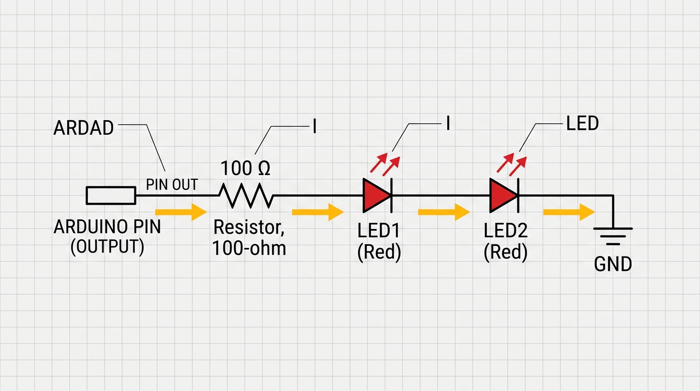
Figure 1: Series circuit diagram where two LEDs share the same current path from one pin.
Parallel Wiring with Individual Resistors
In parallel wiring, each LED gets its own current-limiting resistor. This lets you control the brightness of each LED individually by changing the resistor values. The downside is that the current draws add together. If you connect three LEDs drawing 20 milliamps each, they will pull a total of 60 milliamps from the pin.
Since an Arduino pin can safely supply a maximum of 40 milliamps, driving three standard LEDs in parallel directly from one pin will overload it. To get around this, you can lower the current to 10 milliamps per LED. Modern high-efficiency LEDs are still very bright at this level, and it allows you to safely run up to four LEDs in parallel from a single pin.
C++ Source
1
2
3
4
5
6
7
8
9
10
11
12
const int ledPin = 9; // Connect multiple LEDs, each with its own resistor

void setup() {
  pinMode(ledPin, OUTPUT);
}

void loop() {
  digitalWrite(ledPin, HIGH); // Turn on all parallel LEDs safely
  delay(1000);
  digitalWrite(ledPin, LOW);
  delay(1000);
}
Here is the parallel wiring schematic where each LED has its own resistor to keep the current safe:
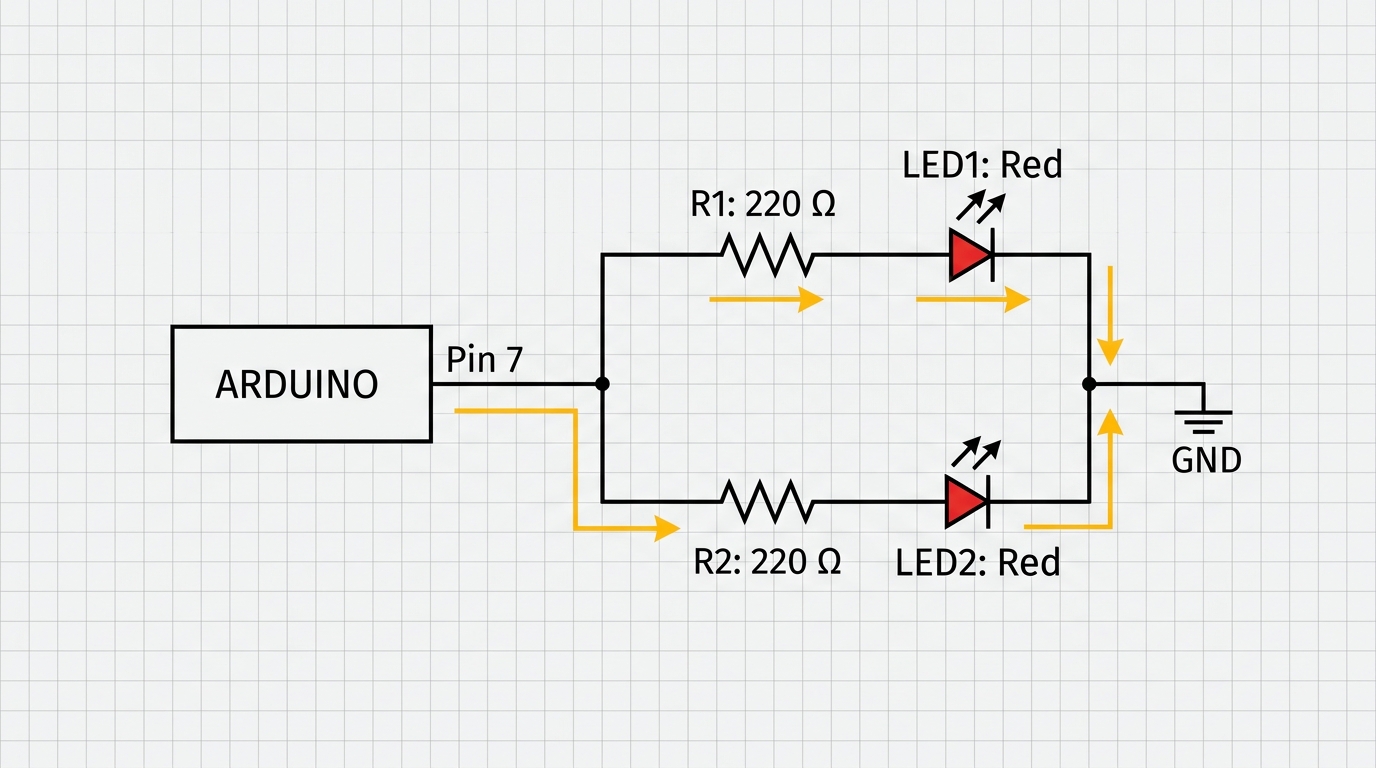
Figure 2: Parallel circuit diagram where each LED branch has its own current-limiting resistor.
Transistor as a Switch
If you need to drive more than a few LEDs, you should use a transistor. A small NPN transistor, like the 2N2222, can switch hundreds of milliamps safely. In this setup, the Arduino pin connects to the transistor's base pin through a 1k-ohm resistor to turn it on or off.
When the Arduino pin goes HIGH, the transistor turns on, connecting the LEDs to ground. This allows the LEDs to draw power directly from the 5V supply rail rather than through the Arduino pin. This protecting buffer lets you drive dozens of LEDs from one pin. The main trade-off is that you need to add a transistor and more resistors to your circuit board.
C++ Source
1
2
3
4
5
6
7
8
9
10
11
12
const int transistorPin = 3; // Connects to the base of the transistor

void setup() {
  pinMode(transistorPin, OUTPUT);
}

void loop() {
  digitalWrite(transistorPin, HIGH); // Turn on transistor to light all LEDs
  delay(2000);
  digitalWrite(transistorPin, LOW);  // Turn off all LEDs
  delay(2000);
}
To help you visualize how to hook this up, here is the schematic layout for a transistor-based LED switch:
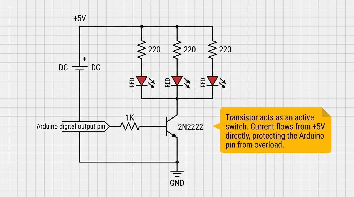
Figure 3: Using an NPN transistor to switch multiple LEDs from the 5V rail using a single control pin.
Charlieplexing
The concept of Charlieplexing was first introduced in 2001 by Maxim Integrated and named after Charles Allen, the applications engineer who proposed it. This method takes advantage of the fact that microcontroller pins can be set to three states: HIGH, LOW, or high-impedance INPUT mode.
With Charlieplexing, the number of LEDs you can drive follows the formula: pins squared minus pins. This means 3 pins can drive 6 LEDs, 4 pins can drive 12 LEDs, and 8 pins can drive 56 LEDs. This is much more efficient than traditional matrix wiring, which requires many more control lines.
C++ Source
1
2
3
4
5
6
7
8
9
10
11
12
13
14
15
16
17
18
19
20
21
22
23
24
25
26
27
// Pin definitions for Charlieplexing matrix
const int PIN_A = 2;
const int PIN_B = 3;
const int PIN_C = 4;

void setup() {
  // Set all pins to INPUT (high impedance) initially
  pinMode(PIN_A, INPUT);
  pinMode(PIN_B, INPUT);
  pinMode(PIN_C, INPUT);
}

void lightLED1() {
  // Light LED1 (Anode to PIN_A, Cathode to PIN_B)
  pinMode(PIN_A, OUTPUT);
  digitalWrite(PIN_A, HIGH);
  pinMode(PIN_B, OUTPUT);
  digitalWrite(PIN_B, LOW);

  // PIN_C remains high-impedance INPUT
  pinMode(PIN_C, INPUT);
}

void loop() {
  lightLED1();
  delay(1000);
}
Charlieplexing works by connecting LEDs in opposite pairs between the pins. For example, LED 1 connects anode-to-A and cathode-to-B, while LED 2 connects cathode-to-A and anode-to-B. To light up a specific LED, you set its anode pin HIGH, its cathode pin LOW, and turn all other pins to INPUT mode so they act disconnected.
To help you understand this matrix wiring, look at this 3-pin Charlieplexing schematic:
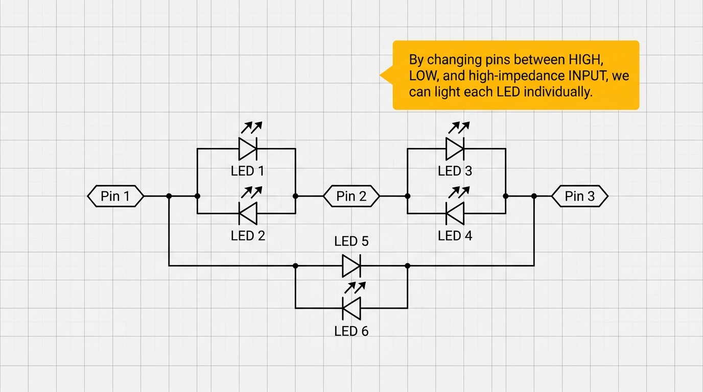
Figure 4: Charlieplexing matrix showing how 3 pins drive 6 LEDs by using complementary pairs.
Only one LED can be lit at a time. To make multiple LEDs look like they are on at once, you must flash them rapidly one after another. This flashing must happen faster than 50 Hz so human eyes do not see any flickering. You also need to match the LED colors, as mixing colors with different voltage requirements can cause the wrong LEDs to light up.
Recommended Approach
If you only need to drive two LEDs from one pin, use parallel wiring with individual resistors. It is simple and requires no extra hardware. For three to ten LEDs, use a transistor switch to protect the microcontroller from drawing too much current.
For more than ten LEDs, consider Charlieplexing or using a dedicated driver chip like the MAX7219. The MAX7219 can drive up to 64 individual LEDs using only three communication pins on your Arduino. It handles all the complex multiplexing and current limiting automatically. For most beginner projects, a simple transistor or parallel resistors will be the easiest and most reliable solution.
Categories for this post
Tags
#led #wiring #beginner #arduino

About The Author
Muhammad Ichsanul FadhilI am a 21-year-old IoT enthusiast who loves microcontrollers and exploring new components. I built IoTSimulator to help beginners learn without needing a pile of hardware.