Tutorial5 min read
How to Use the Built-in LED on Arduino (and Why Pin 13)
Every Arduino board has a tiny LED connected to pin 13 that you can control without any wiring. Learn why it exists, how to use it for debugging, and its limitations.
Every official Arduino board comes with a tiny surface-mounted LED connected directly to digital pin 13. Labeled "L" on the board, you will find it sitting as a green or orange light right next to the USB connector.
This built-in LED is connected through an onboard current-limiting resistor, meaning you can turn it on and off in your code without connecting any external components or breadboards. When I test a brand-new microcontroller board, writing a simple code to blink this LED is always the very first thing I do to verify the chip is functional.
Looking at your board, you can easily spot this tiny light tucked in right next to the header pins, as shown in the layout below:
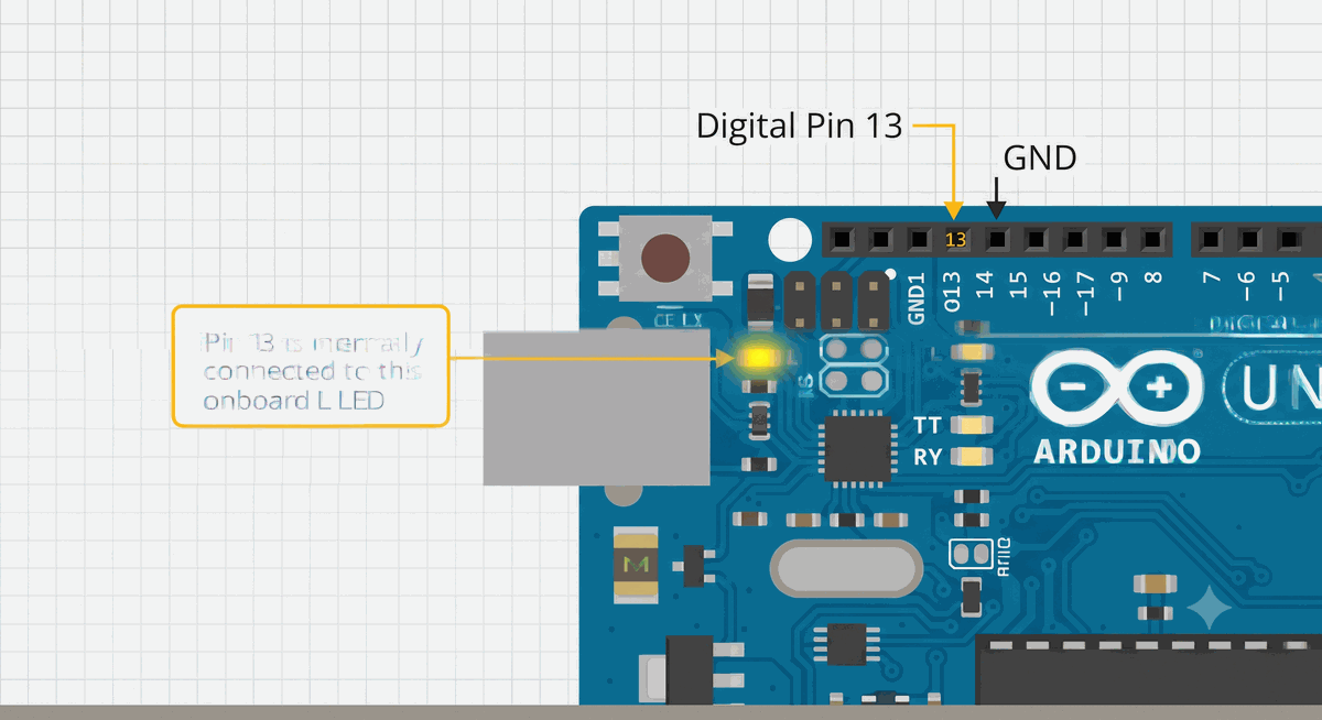
Figure 1: Location of the on-board 'L' LED and Header Pin 13 on the Arduino Uno.
Once you have located the LED on your physical board, controlling it in software is straightforward using Arduino's built-in definitions.
Using LED_BUILTIN Constant
To make your code portable across different Arduino boards, the Arduino environment provides a built-in constant named
LED_BUILTIN. This maps to the correct digital pin for whatever board model you compile for.For the Arduino Uno, Nano, and Mega, this constant maps to pin 13. However, on the MKR board family, it maps to pin 6. By writing
LED_BUILTIN in your sketches, you can run the exact same code on different boards without having to edit the pin numbers manually.C++ Source
1
2
3
4
5
6
7
8
9
10
11
12
13
14
void setup() {
  // Configure the built-in LED pin as an output
  pinMode(LED_BUILTIN, OUTPUT);
}

void loop() {
  // Turn the LED on (HIGH is voltage level)
  digitalWrite(LED_BUILTIN, HIGH);
  delay(1000);

  // Turn the LED off by making the voltage LOW
  digitalWrite(LED_BUILTIN, LOW);
  delay(1000);
}
To understand what happens behind the scenes when you trigger this pin in your code, here is the basic schematic of the on-board LED connection:
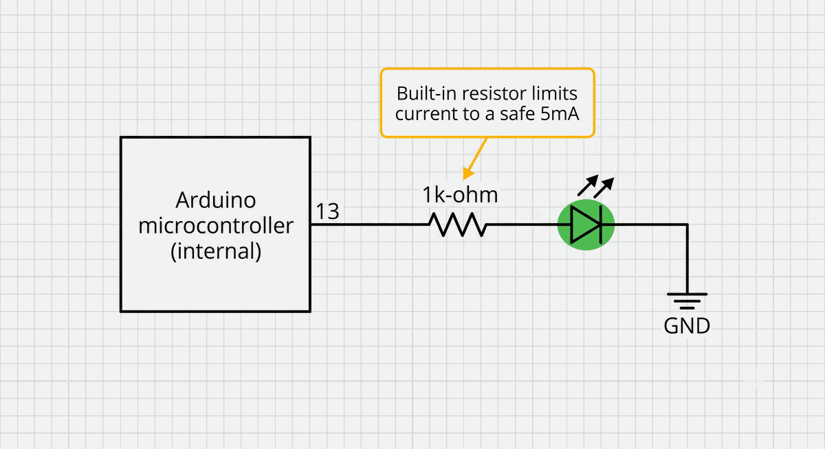
Figure 2: Internal connection showing how Pin 13 routes through a current-limiting resistor to the LED.
This simple setup protects the microcontroller from overcurrent. It is this basic circuit layout that makes Pin 13 so reliable for visual troubleshooting without needing an external breadboard.
Debugging in the Field
The built-in LED is an excellent tool for troubleshooting code when you don't have access to a computer and the Serial Monitor. I often write flashing sequences to indicate different program states or catch bugs.
For instance, you can program a slow, steady blink to show the system is waiting for sensor inputs, and trigger a rapid, double-blink pattern if a sensor error is encountered. Using these simple timing intervals, you can translate complex code logic into clear visual signals, as mapped in this pattern guide:
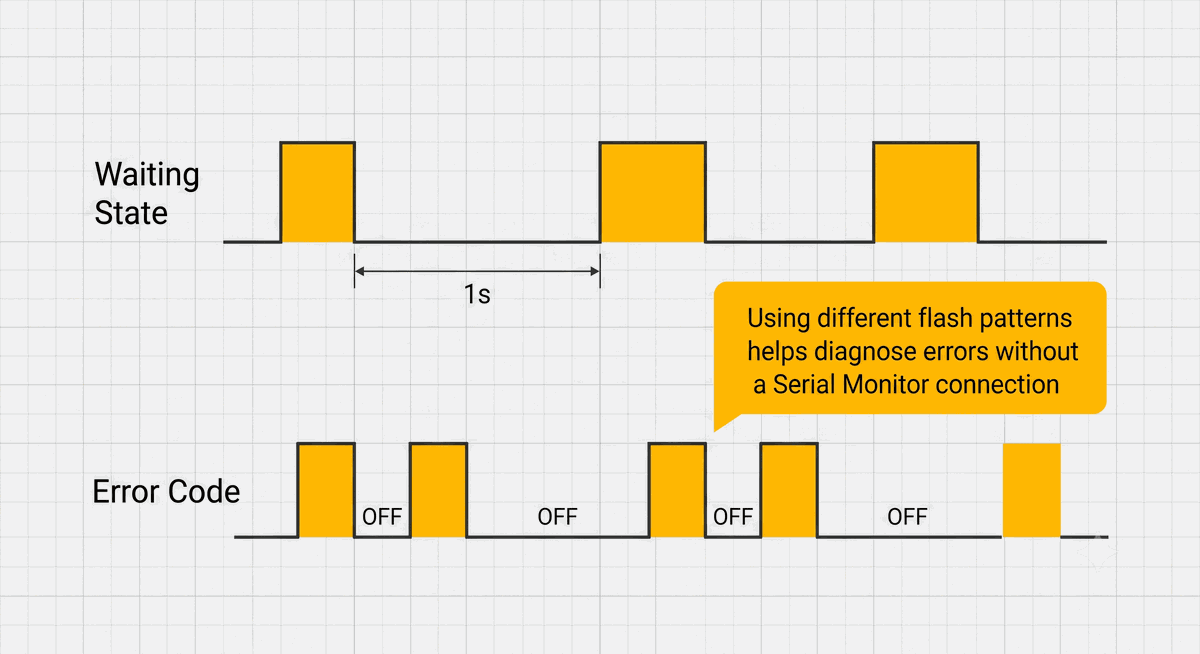
Figure 3: Common LED blinking patterns used for diagnostics and error reporting.
By standardizing these visual signals, you can quickly diagnose sensor or logic states at a single glance without writing extensive serial output routines.
Pro-Tip: You can placedigitalWrite(LED_BUILTIN, HIGH)at the start of a complex function, andLOWat the end. If the LED stays on permanently, you know the program is hanging inside that specific block of code.
Key Limitations to Keep in Mind
While convenient, the built-in LED has some hardware limitations. Since it shares pin 13 with the SPI clock (SCK) signal on standard Arduino boards, the LED will flicker whenever you send data to SPI sensors or SD card readers. This is normal and doesn't damage the board, but it can be distracting.
Additionally, you cannot dim the built-in LED using
analogWrite() on most boards because pin 13 is not a hardware PWM pin. The LED is strictly binary—either fully on or fully off. If you need adjustable brightness, you will need to wire an external LED to a PWM pin instead.Why Was Pin 13 Chosen?
Pin 13 was selected during the early design phase of the original Arduino boards in the mid-2000s. Placing the LED close to the reset switch and USB port made it highly visible, and connecting it to the hardware SPI bus meant developers could see clock activity visually.
On standard Arduino boards, the built-in series resistor limits the LED current to about 3 to 5 milliamps. This keeps the LED glowing comfortably without pulling too much current from the microcontroller's pin limit, leaving plenty of power for other connected sensors.
Categories for this post
Tags
#led #beginner #arduino

About The Author
Muhammad Ichsanul FadhilI am a 21-year-old IoT enthusiast who loves microcontrollers and exploring new components. I built IoTSimulator to help beginners learn without needing a pile of hardware.