Tutorial9 min read
Understanding PWM — Dim an LED and Control a Servo
Pulse width modulation lets you control brightness, speed, and position with just one digital pin. Learn how PWM works on Arduino and build two projects: a dimmable LED and a servo positioner.

Pulse-width modulation, or PWM, is a clever technique that allows digital pins to control analog-style devices. Instead of physically varying the output voltage, we toggle the signal between HIGH and LOW at high speeds. The connected component responds to the average voltage delivered over time.
For instance, an LED running at a 50% duty cycle appears about half as bright. Similarly, a DC motor running at a 50% duty cycle spins at roughly half of its maximum speed. Even though the output pin is only ever fully ON or fully OFF, the load filters this rapid switching into a steady average signal.
According to Wikipedia, the concepts underlying PWM date back to the 19th century. Early steam engines used mechanical pulse modulation to regulate intake valves. Today, modern microcontrollers leverage high-speed semiconductor switches to toggle signals in nanoseconds, losing almost no power as heat in the process.
Understanding Duty Cycle and Frequency
The two main values that define a PWM signal are its **duty cycle** and **frequency**. The duty cycle is the percentage of time the pulse stays HIGH during one full on-off cycle. A 0% duty cycle is always LOW (off), while 100% is always HIGH (on).
To help visualize how changing the duty cycle changes the average voltage, look at these standard waveforms:
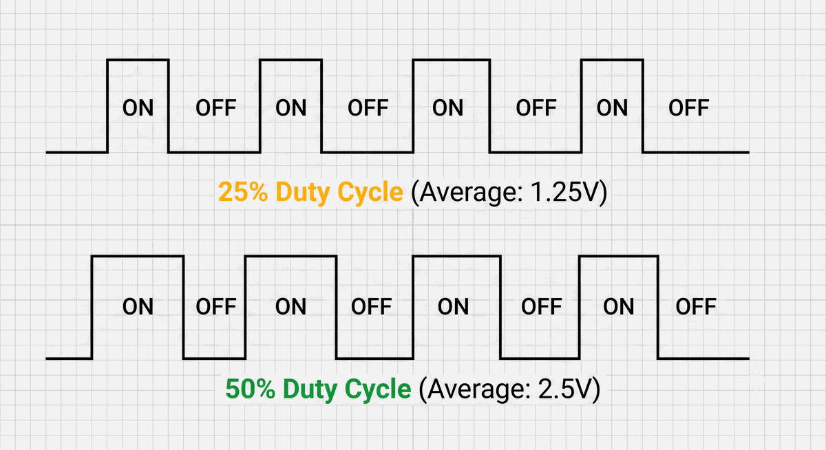
Figure 1: Comparison of different PWM duty cycles and their equivalent average voltages.
As you can see, the average voltage stays directly proportional to the percentage of time the wave is active. This simple timing pattern is what allows a binary digital pin to simulate varying analog outputs.
Frequency is how many times per second the signal repeats. On an Arduino Uno, digital pins 5 and 6 toggle at about 980 Hz, while pins 3, 9, 10, and 11 toggle at 490 Hz. These high speeds prevent any noticeable flickering in LEDs or motor jitter.
When calling
analogWrite(pin, value) in Arduino, the value is an 8-bit integer between 0 and 255. A value of 0 yields a 0% duty cycle, 128 gives a 50% duty cycle, and 255 outputs a 100% duty cycle. The mapping is completely linear, making it easy to calculate intermediate average voltages.Project 1: Dimming LEDs with PWM
When you dim an LED using PWM, the LED actually turns completely on and off hundreds of times per second. Our eyes do not perceive the flashing because it happens far faster than the 60 Hz flicker threshold of human vision. Instead, our brains average out the flashes into a steady, dim glow.
In this simple project, we read a potentiometer's analog position and map it to control the brightness of a connected LED. Since
analogRead() gives a 10-bit value (0-1023) and analogWrite() takes an 8-bit value (0-255), we divide the sensor value by 4 to scale it down.Follow this wiring schematic to connect the potentiometer and LED to your Arduino board:
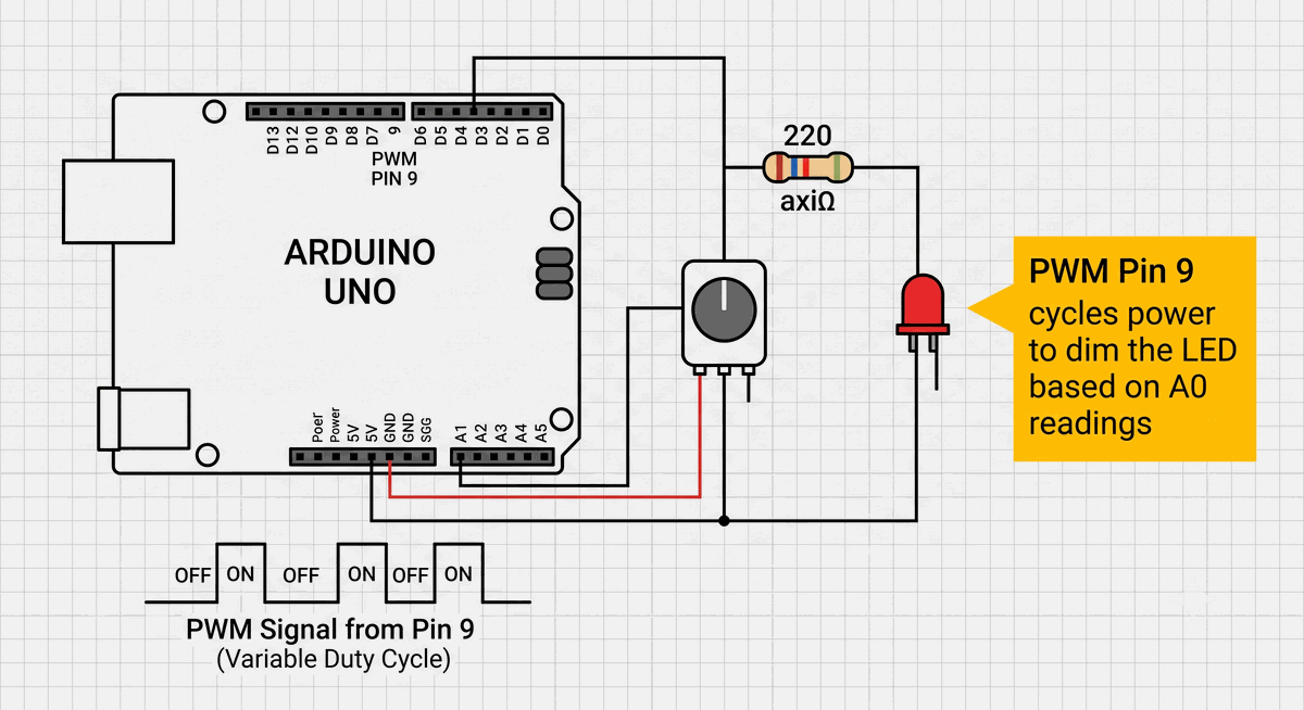
Figure 2: Potentiometer connected to Pin A0 and LED connected to PWM Pin 9.
Once the hardware layout is ready, upload the following program to read the analog knob position and adjust the LED duty cycle in real-time:
C++ Source
1
2
3
4
5
6
7
8
9
10
11
12
13
14
const int potPin = A0; // Potentiometer connected to analog pin A0
const int ledPin = 9;  // LED connected to PWM-capable pin 9

void setup() {
  pinMode(ledPin, OUTPUT);
}

void loop() {
  int potVal = analogRead(potPin);            // Read value between 0 and 1023
  int brightness = map(potVal, 0, 1023, 0, 255); // Scale down to 0-255

  analogWrite(ledPin, brightness);            // Output the PWM duty cycle
  delay(10);                                  // Small stabilization delay
}
If you ever need to convert a PWM signal into a true, smooth analog voltage rather than a pulsed signal, you can pass it through a low-pass filter. This simple circuit uses a resistor and a capacitor to filter out the high-frequency switching, leaving a clean average DC voltage behind.
Project 2: Controlling Servos with PWM
Servo motors use a modified form of PWM called Pulse-Position Modulation. Instead of using the percentage of active time (duty cycle) to control power, the servo looks at the absolute width of the pulse (measured in milliseconds) to determine its physical angle.
A standard servo expects a pulse every 20 milliseconds (a 50 Hz frequency). A pulse width of exactly 1.0 ms commands the servo to move to 0 degrees, 1.5 ms centers it at 90 degrees, and 2.0 ms rotates it to 180 degrees.
Refer to this wiring diagram to connect your servo motor to the Arduino:
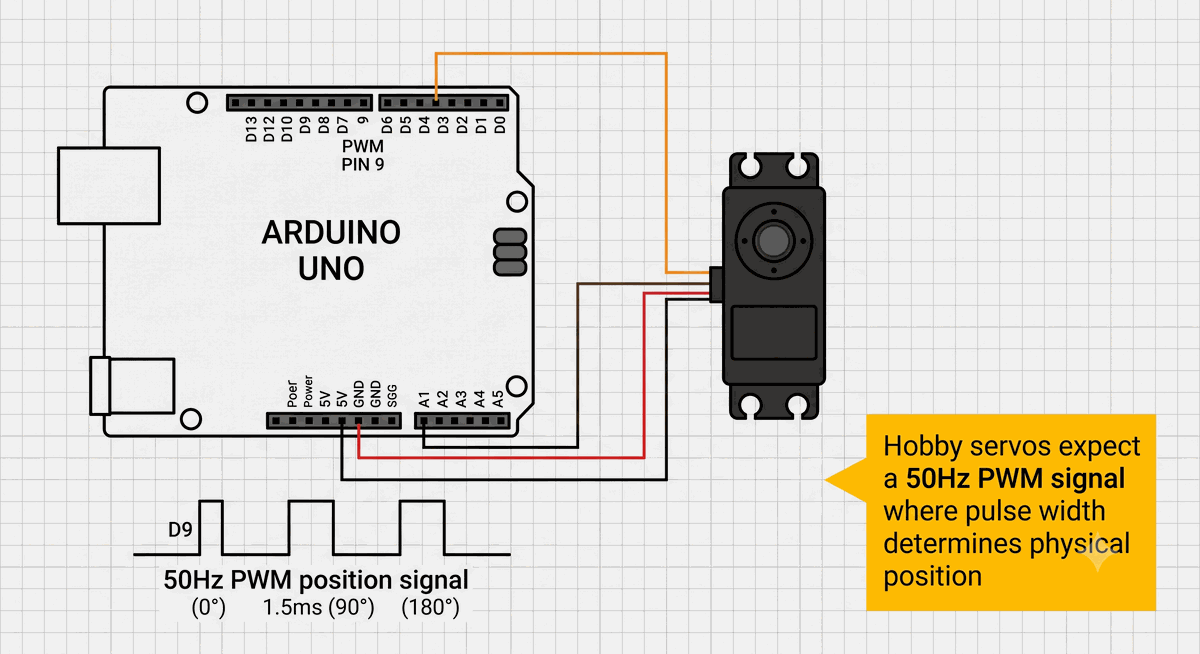
Figure 3: Servo motor signal pin connected to Digital Pin 9 with external power rails.
To control the angle of the servo motor with your potentiometer knob, upload this code to your Arduino board:
C++ Source
1
2
3
4
5
6
7
8
9
10
11
12
13
14
15
16
17
#include <Servo.h>

Servo myServo;         // Create a servo control object
const int potPin = A0; // Control knob on pin A0
const int servoPin = 9; // Servo signal pin

void setup() {
  myServo.attach(servoPin); // Attaches the servo on pin 9 to the object
}

void loop() {
  int potVal = analogRead(potPin);
  int angle = map(potVal, 0, 1023, 0, 180); // Map analog input to degrees

  myServo.write(angle);                     // Send command to the servo
  delay(15);                                // Wait for the servo to travel
}
The Arduino
Servo library handles all this complex timing automatically. When you write an angle, the library calculates and maintains the pulses in the background. Because the library uses software interrupts, you can run a servo on any digital pin, not just the hardware PWM pins.Real-World PWM Applications
PWM is used in many industries. Switched-mode power supplies adjust their duty cycle in real-time to regulate voltage output. Variable-frequency motor drives use high-power PWM to control large industrial motors with efficiency rates exceeding 98%.
Audio amplifiers also leverage PWM. Class D amplifiers convert audio waves into a high-frequency PWM signal, which is then passed through a low-pass filter to recover the sound. Because the transistors switch fully on and off instead of running in a partially open state, Class D amplifiers lose very little energy, making them ideal for battery-powered devices like smartphones.
In the IoTSimulator, you can test PWM on all boards. The virtual Arduino Uno supports all 6 PWM pins with their exact hardware frequencies. The ESP32-C3 simulator supports PWM on all GPIO pins using the LEDC peripheral, which lets you program custom frequencies from 1 Hz up to several Megahertz.
Common PWM Mistakes
Confusing
analogWrite() with a true analog voltage is the most common beginner mistake. Unless you add a low-pass filter, the pin is only ever outputting 5V or 0V. An oscilloscope would show a square wave, not a flat line.Another common mistake is omitting a resistor when dimming an LED with PWM. Even though the average voltage is low, the instantaneous voltage is still the full 5V. Without a current-limiting resistor, the peak current will exceed the LED's safe ratings and damage it over time. Always calculate your resistor values based on the maximum supply voltage.
Categories for this post
Tags
#pwm #led #servo #beginner #arduino

About The Author
Muhammad Ichsanul FadhilI am a 21-year-old IoT enthusiast who loves microcontrollers and exploring new components. I built IoTSimulator to help beginners learn without needing a pile of hardware.