Tutorial10 min read
From Blink to IoT: Your First 5 Arduino Projects
Five beginner-friendly Arduino projects that teach the core concepts of electronics and programming - from a simple blinking LED to a distance-sensing alert system you can run in the simulator right now.
Every expert maker started with a single blinking LED. It sounds like a cliche, but it is absolutely true. The first time you write a sketch, upload it to a board, and see a physical light turn on and off by your own command - that is the moment that changes how you see hardware forever.
This article walks you through five starter projects that build on each other step-by-step. Each project introduces a core concept: digital output, digital input, analog readings, sensor protocols, and pulse timing. By the end of this guide, you will have a solid foundation to combine these ideas into your own unique creations.
Best of all, all five projects can be run directly in the IoTSimulator. You do not need a single physical wire or sensor to follow along with these tutorials.
Project 1: LED Blink
The classic starting point for any electronics beginner is the blink sketch. An LED connected to digital pin 13 turns on, waits, turns off, and repeats the cycle. This project teaches the most basic output operation using the controller.
You can read more about the LED component guide for wiring details and polarity information. We use three basic commands:
pinMode(), digitalWrite(), and delay().C++ Source
1
2
3
4
5
6
7
8
9
10
11
12
const int ledPin = 13;

void setup() {
  pinMode(ledPin, OUTPUT);
}

void loop() {
  digitalWrite(ledPin, HIGH);
  delay(500);
  digitalWrite(ledPin, LOW);
  delay(500);
}
To help you wire this up, here is the connection diagram showing how to attach the LED and resistor to your Arduino:
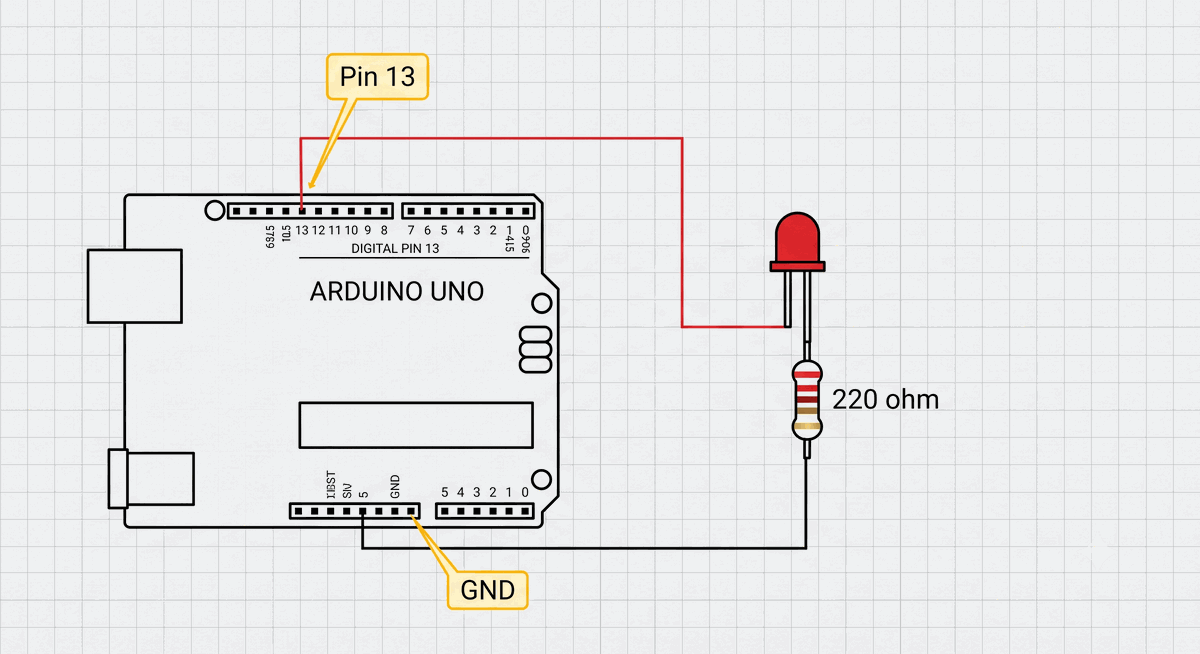
Figure 1: Basic LED blink circuit wiring with a current-limiting resistor connected to Pin 13.
At 500 milliseconds, the LED blinks at a comfortable pace. You can change the delay numbers to make it blink faster or slower. The key takeaway here is that the Arduino repeats the
loop() function forever, so your output keeps cycling without needing any extra code.What you learn: digital output, pin mode setup, and basic timing with delay.
Project 2: Pushbutton + LED
Now we add a digital input. A pushbutton tells the Arduino whether it is currently pressed or released, and we program the LED to respond to that state. This introduces the
digitalRead() function and basic conditional logic.C++ Source
1
2
3
4
5
6
7
8
9
10
11
12
13
14
15
16
const int buttonPin = 2;
const int ledPin = 13;

void setup() {
  pinMode(buttonPin, INPUT_PULLUP);
  pinMode(ledPin, OUTPUT);
}

void loop() {
  int buttonState = digitalRead(buttonPin);
  if (buttonState == LOW) {
    digitalWrite(ledPin, HIGH);
  } else {
    digitalWrite(ledPin, LOW);
  }
}
To wire up the button and LED to your Arduino, refer to the wiring diagram below:
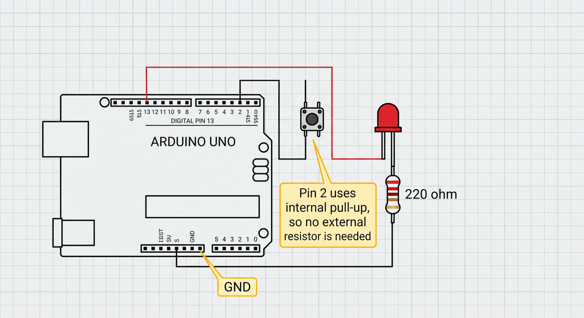
Figure 2: Pushbutton connected to digital Pin 2 and LED connected to Pin 13.
Using
INPUT_PULLUP enables the Arduino's internal resistor. This reads HIGH when the button is open and LOW when it is pressed. This handy feature avoids adding an external resistor, keeping your breadboard wiring simple. The if statement checks the button state and decides whether to send a HIGH or LOW signal to the LED.What you learn: digital input, internal pull-up resistors, and conditional logic.
Project 3: Potentiometer + Serial Monitor
A potentiometer is a variable resistor that acts as an analog knob. Turning the knob changes the voltage on an analog pin, and the Arduino converts that voltage into a number between 0 and 1023. Reading that number with
analogRead() and printing it to the Serial Monitor teaches you how to measure variable inputs.The potentiometer component guide explains voltage dividers and the
analogRead() function in more depth.C++ Source
1
2
3
4
5
6
7
8
9
10
11
const int potPin = A0;

void setup() {
  Serial.begin(9600);
}

void loop() {
  int sensorValue = analogRead(potPin);
  Serial.println(sensorValue);
  delay(100);
}
Connect your potentiometer to the analog pin by matching the pins in this layout:
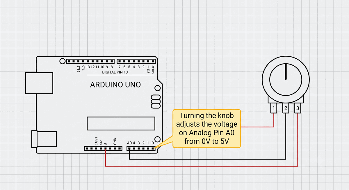
Figure 3: Potentiometer wiper pin connected to Analog Pin A0 with VCC and GND connections.
Open the Serial Monitor after uploading this sketch. Turn the potentiometer knob and watch the numbers flow. A value of 0 means the knob is turned all the way to one side, 1023 means the other, and the values in between represent positions along the rotation. This is the foundation for reading all analog sensors, like light or temperature sensors.
What you learn: analog input, serial communication, and voltage-to-number conversion.
Project 4: DHT22 Temperature Monitor
The DHT22 sensor measures temperature and humidity using a single digital data line. Unlike a simple analog sensor, it uses a timed digital protocol that requires a library. This project introduces you to reading real-world environment data.
Visit the DHT22 component guide for a complete walkthrough of wiring, code, and troubleshooting.
C++ Source
1
2
3
4
5
6
7
8
9
10
11
12
13
14
15
16
17
18
19
20
21
22
23
24
25
26
27
28
29
#include <DHT.h>

#define DHTPIN 2
#define DHTTYPE DHT22

DHT dht(DHTPIN, DHTTYPE);

void setup() {
  Serial.begin(9600);
  dht.begin();
}

void loop() {
  float h = dht.readHumidity();
  float t = dht.readTemperature();

  if (isnan(h) || isnan(t)) {
    Serial.println("Sensor error");
    delay(2000);
    return;
  }

  Serial.print("Humidity: ");
  Serial.print(h);
  Serial.print("%  Temperature: ");
  Serial.print(t);
  Serial.println("C");
  delay(2000);
}
To establish a clean connection with the sensor pinout, use this wiring schematic:
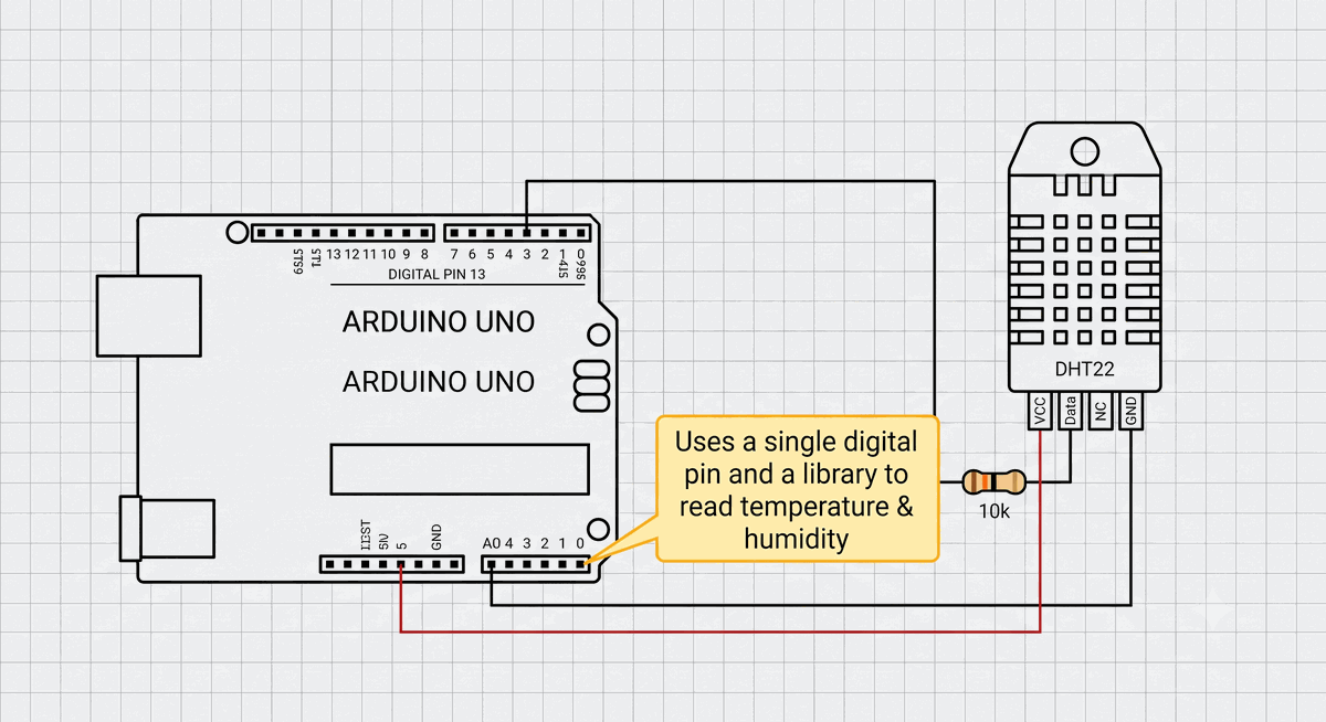
Figure 4: DHT22 digital sensor connected to Pin 2 with power rails.
The DHT library handles the complex timing protocol so you do not have to write it yourself. The sensor needs about two seconds between readings to stabilize, which is why we use a 2000 ms delay. The
isnan() check catches communication failures. If the sensor does not respond, the sketch prints an error instead of displaying incorrect values.What you learn: sensor libraries, digital communication protocols, and error checking.
Project 5: HC-SR04 Distance Alert
The HC-SR04 ultrasonic sensor measures distance by sending a sound pulse and timing how long the echo takes to return. The Arduino triggers the sensor, measures the echo pulse width with
pulseIn(), and converts the time into centimeters. A buzzer changes its beep speed based on how close an object is.You can run the full parking distance alert project in the simulator, or check the HC-SR04 component guide for detailed wiring and code examples.
C++ Source
1
2
3
4
5
6
7
8
9
10
11
12
13
14
15
16
17
18
19
20
21
22
23
24
25
26
27
28
29
30
31
32
33
34
35
36
const int trigPin = 9;
const int echoPin = 10;
const int buzzerPin = 8;

void setup() {
  pinMode(trigPin, OUTPUT);
  pinMode(echoPin, INPUT);
  pinMode(buzzerPin, OUTPUT);
  Serial.begin(9600);
}

void loop() {
  digitalWrite(trigPin, LOW);
  delayMicroseconds(5);
  digitalWrite(trigPin, HIGH);
  delayMicroseconds(10);
  digitalWrite(trigPin, LOW);

  long duration = pulseIn(echoPin, HIGH);
  float distance = duration * 0.0343 / 2;

  Serial.print("Distance: ");
  Serial.print(distance);
  Serial.println(" cm");

  if (distance < 10) {
    tone(buzzerPin, 1000);
  } else if (distance < 25) {
    tone(buzzerPin, 1000);
    delay(80);
    noTone(buzzerPin);
    delay(80);
  }

  delay(200);
}
Refer to this complete wiring schematic to hook up the sensor and buzzer to the board:
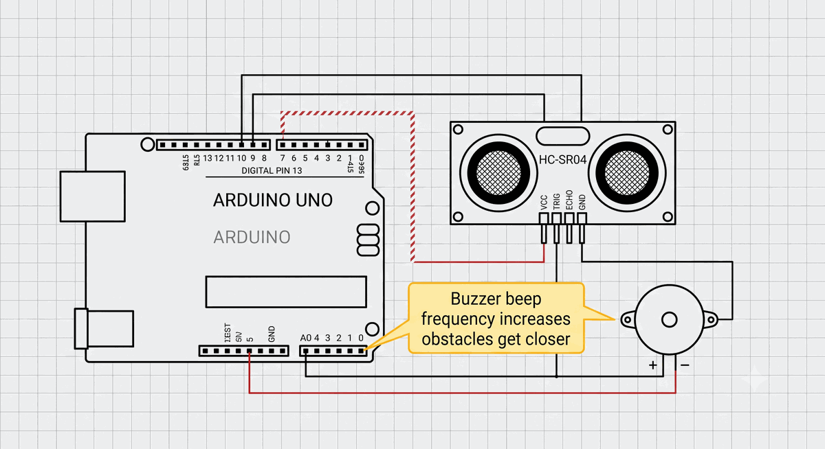
Figure 5: HC-SR04 ultrasonic sensor and buzzer connected to the Arduino Uno.
The speed of sound in air is about 343 meters per second, or 0.0343 centimeters per microsecond. The division by 2 converts the round-trip time into a one-way distance. This same principle is used in real parking sensors, robot obstacle avoidance, and tank level monitors.
What you learn: ultrasonic ranging, pulse timing, and alert logic.
What Is Next?
These five projects cover the essential patterns of Arduino programming. You can now control outputs, read inputs, communicate over serial, use libraries, and measure the environment. Every complex project is built from combinations of these same ideas.
Browse the project library for more ideas. Try combining two projects: use the potentiometer to control the blink speed of the LED, or trigger the distance alert with a pushbutton. The simulator makes it safe to experiment - you cannot break anything, and you can reset the circuit in one click.
Categories for this post
Tags
#arduino #beginner #projects #tutorial #LED #pushbutton #potentiometer #DHT22 #HC-SR04

About The Author
Muhammad Ichsanul FadhilI am a 21-year-old IoT enthusiast who loves microcontrollers and exploring new components. I built IoTSimulator to help beginners learn without needing a pile of hardware.