Blink an LED with an ESP32-C3

Live project track
Every microcontroller project begins with the classic 'Hello World' of electronics: making an LED blink. It is the fastest, clearest way to verify that your development board is alive, your wiring is correct, and your firmware is running. On commercial IoT gadgets, this same blinking signal functions as a heartbeat indicator to show that the system is operating normally.
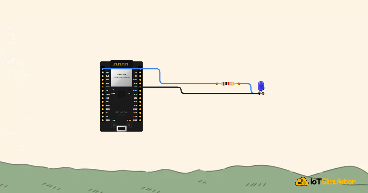
In this project, you will build a digital output circuit using an ESP32-C3 DevKit, a 220Ω resistor, and a blue 5mm LED. The main idea is that the ESP32-C3 controls GPIO 7 as a digital output, switching between 3.3 volts (HIGH) and 0 volts (LOW) every half second while printing live timestamps to the serial monitor.
How Digital Pins Control an LED
General Purpose Input/Output (GPIO) pins are the primary way a microcontroller interacts with external electronics. When configured as an output, a pin can be switched electronically between two voltages: 3.3V (HIGH) or 0V (LOW). Setting the pin to HIGH delivers current to turn the LED on, while setting it to LOW cuts off the current to turn the LED off.
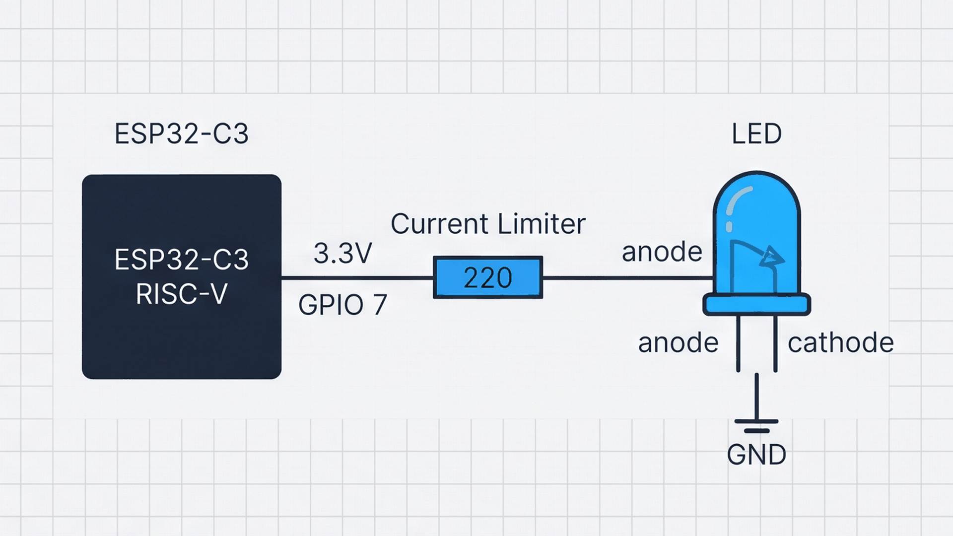
The diagram above illustrates the complete current loop. When GPIO 7 is set to HIGH, current flows out of the pin, passes through the 220Ω resistor, enters the blue LED's anode (+), and returns through the cathode (−) into GND. The resistor is essential: without it, too much current would rush through the LED, risking permanent damage to both the LED and the microcontroller pin.
| Pin state | Output voltage | Current flow | LED appearance |
|---|---|---|---|
| HIGH | 3.3 V | Current flows through resistor and LED to GND | Illuminated (ON) |
| LOW | 0.0 V | No voltage difference across the circuit | Dark (OFF) |
Unlike older 5V boards such as the classic Arduino Uno, modern microcontrollers like the ESP32-C3 operate on 3.3V logic. Blue LEDs typically need around 3.0 to 3.1 volts to illuminate. With a 3.3V supply and a 220Ω resistor, the LED shines brightly while drawing less than 1 milliamp of current.
Understanding Blink Timing and Serial Logs
Blinking requires precise timing. By setting the pin HIGH for 500 milliseconds and LOW for 500 milliseconds, the circuit completes one full ON/OFF cycle every 1000 milliseconds (exactly 1.0 second). In physics terms, this repeating rhythm has a frequency of 1.0 Hertz.
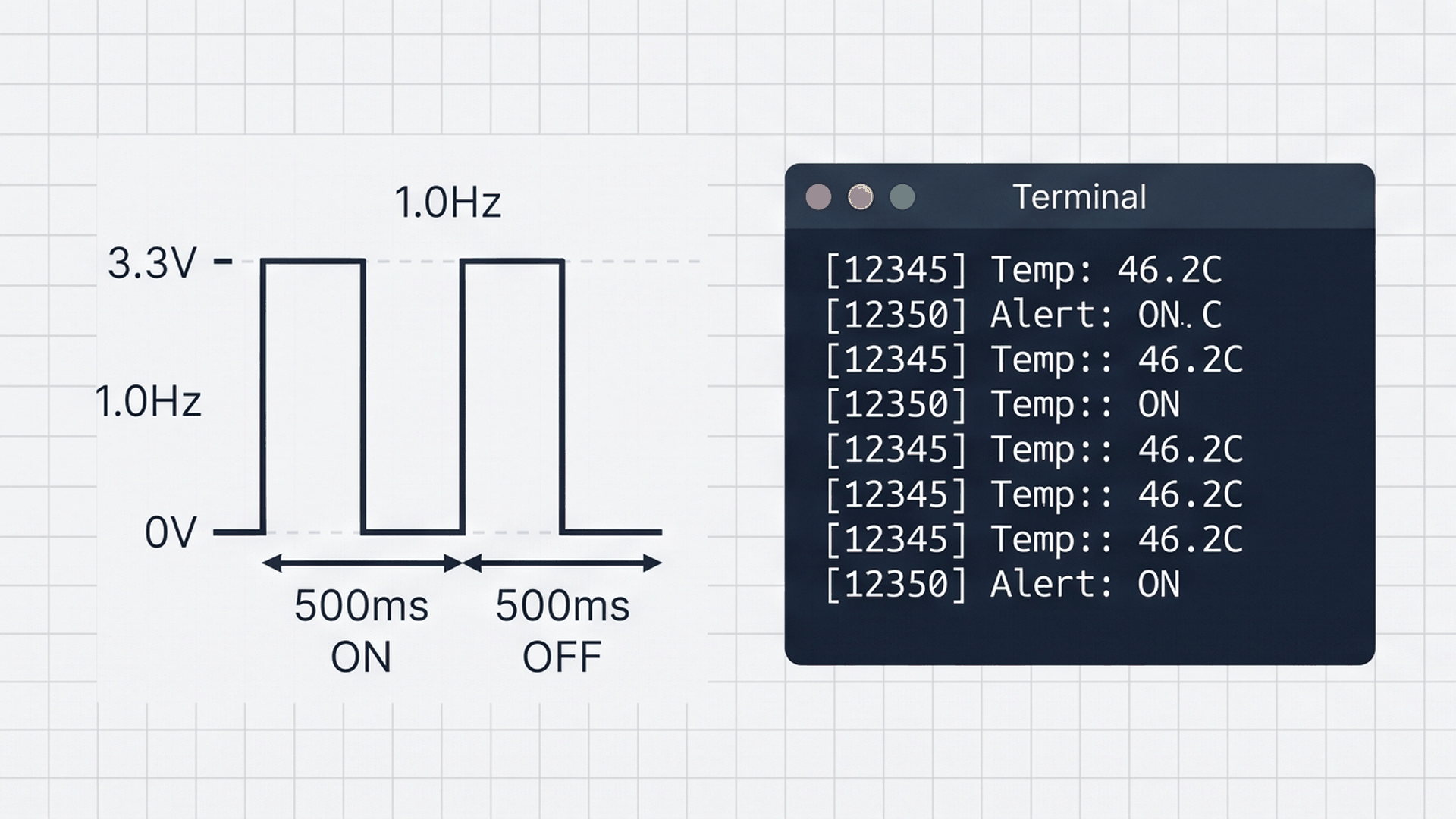
The visual above shows the output voltage waveform alongside the serial monitor terminal. Every time the pin toggles, the firmware prints a timestamped message over the USB cable at 115200 baud. This allows you to verify that your code is executing on schedule, even when working on headless devices without an attached screen.
| Cycle phase | Duration | Voltage on GPIO 7 | Serial log message |
|---|---|---|---|
| Pulse ON | 500 ms | 3.3 V | [T+Xms] LED Status: ON (GPIO 7 -> HIGH) |
| Pulse OFF | 500 ms | 0.0 V | [T+Xms] LED Status: OFF (GPIO 7 -> LOW) |
| Total Period | 1000 ms (1.0 s) | 1.0 Hz Cycle | One full blink repetition |
Using millis() in the log statements lets you see the exact number of milliseconds since the microcontroller powered on, providing an accurate timestamp for every event.
Connecting the Circuit
Wiring an LED to a microcontroller is like connecting a water pipe to a delicate water wheel. You need a restriction in the pipe so the water does not rush through at full speed and destroy the wheel.
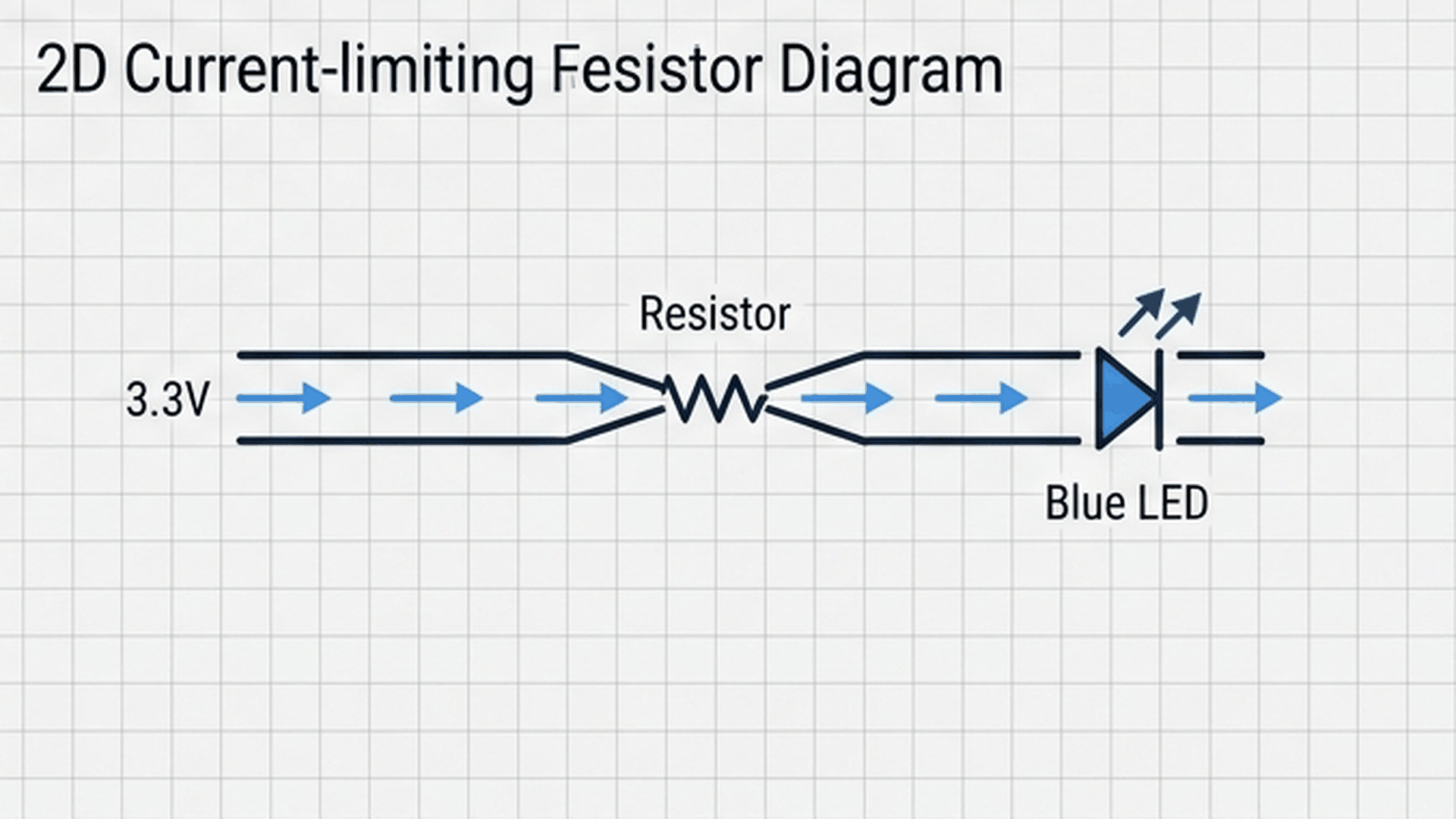
The 220Ω resistor acts as that narrow constriction, keeping the current safely at around 15 milliamps. Wire the LED and resistor to GPIO 7 as detailed in the connection matrix below:
Remember that LEDs are polarized components: current can only pass through them in one direction. If you accidentally plug the LED in backwards, no current will flow and the light will remain completely dark.
Complete Code
Upload the following sketch to your ESP32-C3 DevKit. It configures the pin, initializes serial communication, and blinks the LED in a continuous loop.
// ============================================================================
// ESP32-C3 DevKit RISC-V: Digital Output & Status Indicator Blinking
// Target Pin: GPIO 7 (IO7 on right pin header)
// ============================================================================

#define LED_PIN 7
const unsigned long BLINK_INTERVAL_MS = 500;

void setup() {
  // Configure GPIO 7 as push-pull digital output
  pinMode(LED_PIN, OUTPUT);
  digitalWrite(LED_PIN, LOW);

  // Initialize Serial Monitor at 115200 baud
  Serial.begin(115200);
  delay(200); // Brief settling delay for USB-CDC
  Serial.println(F("==========================================="));
  Serial.println(F("  ESP32-C3 RISC-V LED Blink Initialized    "));
  Serial.println(F("  Microcontroller Clock: 160 MHz           "));
  Serial.println(F("  Target Pin: GPIO 7 (Output)             "));
  Serial.println(F("==========================================="));
}

void loop() {
  // Drive GPIO high (3.3V)
  digitalWrite(LED_PIN, HIGH);
  Serial.print(F("[T+"));
  Serial.print(millis());
  Serial.println(F("ms] LED Status: ON (GPIO 7 -> HIGH)"));
  delay(BLINK_INTERVAL_MS);

  // Drive GPIO low (0V GND)
  digitalWrite(LED_PIN, LOW);
  Serial.print(F("[T+"));
  Serial.print(millis());
  Serial.println(F("ms] LED Status: OFF (GPIO 7 -> LOW)"));
  delay(BLINK_INTERVAL_MS);
}
How the Code Works, Part by Part
The program follows the standard Arduino structure with initialization in setup() and continuous execution in loop().
▸ Pin Declarations and Timing Constants
The sketch begins by declaring which pin to control and defining how long each blink phase should last.
#define LED_PIN 7
const unsigned long BLINK_INTERVAL_MS = 500;
Using #define assigns the pin number once at the top of the sketch. If you move your wire to a different GPIO pin later, you only have to change this single line.
▸ Initializing GPIO and Serial Monitor in setup()
Inside setup(), the microcontroller configures GPIO 7 as an active output and starts the serial communication channel.
pinMode(LED_PIN, OUTPUT);
digitalWrite(LED_PIN, LOW);

Serial.begin(115200);
delay(200);
The pinMode(LED_PIN, OUTPUT) command configures the internal transistors on GPIO 7 so they can supply power to external circuits. Initializing the pin to LOW ensures the LED starts in a known off state.
▸ Blinking and Timestamp Logging in loop()
The loop() function runs over and over for as long as the board has power.
digitalWrite(LED_PIN, HIGH);
Serial.print(F("[T+"));
Serial.print(millis());
Serial.println(F("ms] LED Status: ON (GPIO 7 -> HIGH)"));
delay(BLINK_INTERVAL_MS);

digitalWrite(LED_PIN, LOW);
Serial.print(F("[T+"));
Serial.print(millis());
Serial.println(F("ms] LED Status: OFF (GPIO 7 -> LOW)"));
delay(BLINK_INTERVAL_MS);
The delay() function halts execution for 500 milliseconds between state changes. The F() macro stores text strings directly in flash program memory, saving valuable RAM on the microcontroller.
Fixing Common Problems
If your circuit does not light up or the serial terminal stays blank, check the quick solutions below.
| What you see | Likely cause | What to try |
|---|---|---|
| LED stays completely off | LED plugged in backwards or wrong pin | Verify the long leg of the LED faces GPIO 7 through the resistor; confirm wire is in IO7 |
| Serial monitor shows unreadable gibberish | Baud rate mismatch in serial monitor | Change the serial monitor baud rate dropdown to 115200 baud |
| LED is extremely dim, barely visible | Resistor value too large (e.g., 220 kΩ instead of 220Ω) | Check resistor color bands: Red-Red-Brown represents 220Ω |
| No serial output appears on board reset | USB CDC option disabled in board settings | In Arduino IDE Tools menu, set USB CDC On Boot: Enabled |
A common pitfall with the ESP32-C3 is the serial baud rate. Unlike traditional 9600 baud Arduino Uno projects, ESP32 boards run at 115200 baud by default to handle fast diagnostic messages.
Try It in the Simulator
Click the Start Simulation (▶) button in the top toolbar to begin. The blue LED will immediately start blinking once per second. Click on the Serial Monitor tab in the bottom panel to watch the live timestamped logs stream in as each blink occurs!