Measure Distance with an ESP32-C3 and Ultrasonic Sensor

Live project track
When modern cars back into a parking space, beeps sound faster as the bumper approaches a wall. Robots and smart vacuums use the exact same technique to map rooms without bumping into furniture. These systems rely on ultrasonic distance sensors, which send out pulses of high-frequency sound and measure how long it takes for the echo to bounce back.
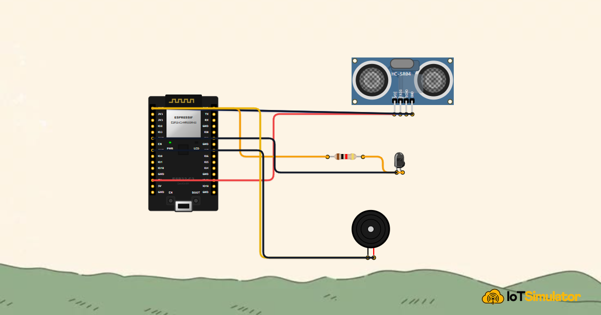
In this project, you will build an interactive distance monitoring station using an ESP32-C3 microcontroller, an HC-SR04 ultrasonic sensor, an amber warning LED, and a piezo buzzer. The main idea is that the ESP32-C3 measures the microsecond round-trip time of ultrasonic sound pulses, calculates the distance in centimeters, plots a live visual graph on the Arduino Serial Plotter, and triggers an audio-visual warning whenever an obstacle gets closer than 15 centimeters.
How Ultrasonic Sound Measures Distance
The HC-SR04 sensor has two metallic cylinders on the front: a transmitter (T) and a receiver (R). When triggered by a brief pulse from the microcontroller, the transmitter fires an inaudible 40kHz sound burst. The wave travels through the air, hits an obstacle, bounces back, and is detected by the receiver.
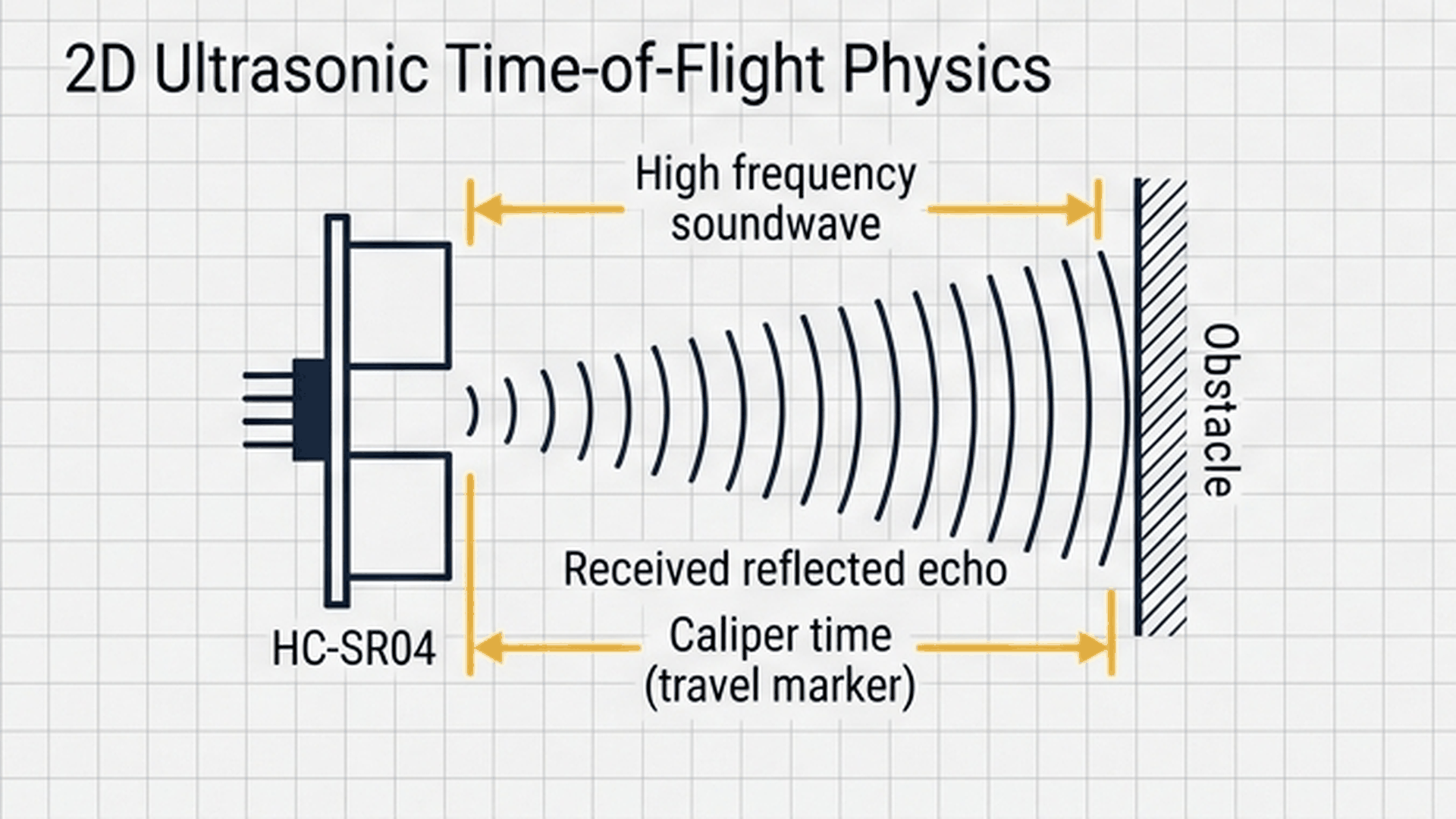
The diagram above illustrates this round-trip journey. Because sound travels through room-temperature air at approximately 343 meters per second (0.0343 cm per microsecond), knowing the travel time lets us calculate the distance directly. Because the sound wave travels to the obstacle and back, we divide the result by 2:
$$\text{Distance (cm)} = \frac{\text{Echo Time (µs)} \times 0.0343}{2}$$
| Obstacle distance | Round-trip echo duration | Echo pulse pin state |
|---|---|---|
| 5.0 cm | ~291 microseconds | Brief HIGH pulse on GPIO 4 |
| 15.0 cm (Threshold) | ~874 microseconds | Medium HIGH pulse on GPIO 4 |
| 30.0 cm | ~1749 microseconds | Long HIGH pulse on GPIO 4 |
| No obstacle detected | Exceeds 30,000 µs timeout | Reports maximum 400.0 cm limit |
Adding a 30,000 microsecond (30 ms) timeout to the measurement function prevents the code from freezing if the sensor points into an empty room or open space where no echo ever returns.
Plotting Distance Graphs and Triggering Alerts
Numbers printed to a text console can be hard to track when an object moves quickly. The Arduino Serial Plotter solves this by turning numerical text streams into live scrolling waveforms in real time.
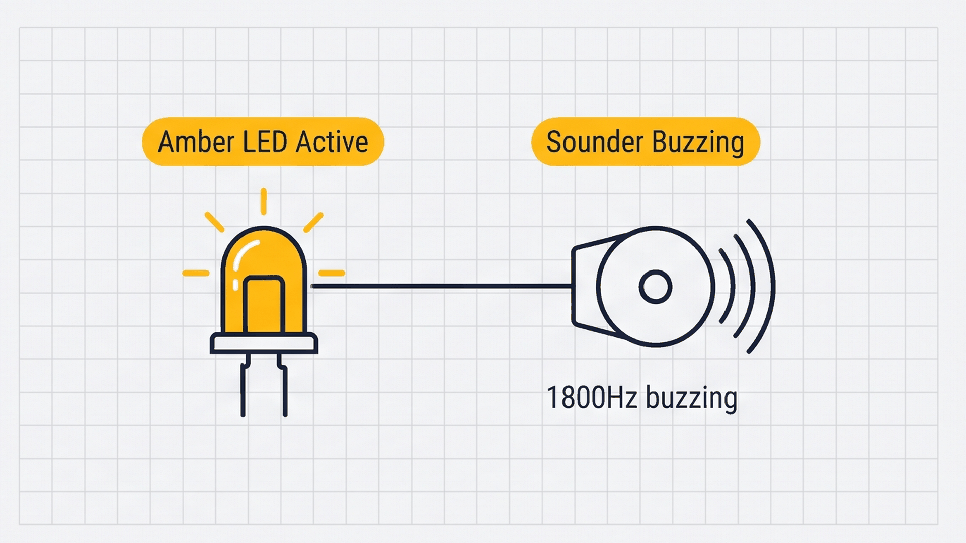
The visual above shows the live graph alongside the alert indicators. The firmware prints two variables side-by-side: Distance_cm and Threshold. The plotter automatically renders the 15cm threshold as a steady horizontal reference line, making it instantly obvious when the live distance curve dips into the danger zone.
| Measured distance | Safety zone | Amber LED (GPIO 5) | Piezo Buzzer (GPIO 6) |
|---|---|---|---|
| Greater than 15.0 cm | Safe Zone | OFF | Silent |
| 15.0 cm or closer | Collision Alert Zone | Illuminated (ON) | Active 1800 Hz beep chirps |
A short 60 millisecond pause between measurement cycles allows lingering sound echoes to die down completely before the next burst fires, preventing phantom reflections from causing false alarms.
Connecting the Circuit
Think of this device like a car's reverse parking sensor. As an obstacle draws nearer, the audible chirps speed up until they merge into a solid warning tone when you are dangerously close.
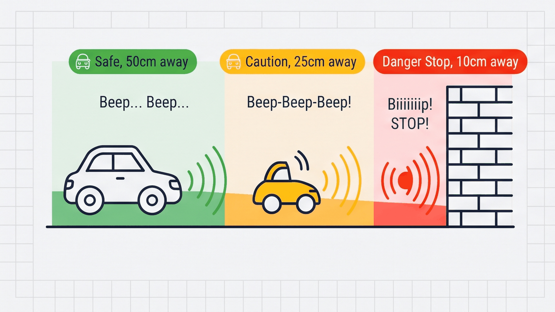
As shown in the parking zone illustration, the sensor continuously monitors obstacle proximity while the LED and buzzer provide tiered feedback. Connect the ultrasonic sensor, alert LED, and buzzer as detailed below:
Next, connect the amber warning LED through a current-limiting resistor to GPIO 2 to provide a clear visual proximity alert:
Finally, wire the piezo buzzer to GPIO 3 to emit acoustic chirps that speed up as objects draw closer to the sensor:
Why does the HC-SR04 connect to 5V instead of 3.3V? The ultrasonic transducer crystals inside the HC-SR04 require 5 volts to generate strong acoustic pressure waves. Powering it from 3.3V will drastically reduce its detection range and cause unstable readings.
Complete Code
Upload the following sketch to your ESP32-C3 DevKit. It triggers the sensor, calculates distance, streams data formatted for the Serial Plotter, and activates the alarms when obstacles cross the 15cm threshold.
// ============================================================================
// ESP32-C3 RISC-V: Ultrasonic Telemetry & Real-Time Serial Plotter
// HC-SR04: TRIG -> GPIO 3, ECHO -> GPIO 4
// Alert Outputs: LED -> GPIO 5, Buzzer -> GPIO 6
// ============================================================================

#define TRIG_PIN 3
#define ECHO_PIN 4
#define LED_PIN  5
#define BUZZ_PIN 6

const float SPEED_OF_SOUND_CM_US = 0.0343; // Speed of sound in dry air at 20°C (cm/µs)
const float PROXIMITY_THRESHOLD_CM = 15.0;

void setup() {
  Serial.begin(115200);
  delay(200);

  pinMode(TRIG_PIN, OUTPUT);
  pinMode(ECHO_PIN, INPUT);
  pinMode(LED_PIN, OUTPUT);
  pinMode(BUZZ_PIN, OUTPUT);

  digitalWrite(TRIG_PIN, LOW);
  digitalWrite(LED_PIN, LOW);

  Serial.println(F("==========================================="));
  Serial.println(F(" ESP32-C3 Ultrasonic Telemetry & Plotter   "));
  Serial.println(F(" Echo Timeout: 30000 µs (~500 cm range)    "));
  Serial.println(F(" Format: Distance_cm:<val>,Threshold:<val> "));
  Serial.println(F("==========================================="));
}

void loop() {
  // Transmit 10 microsecond trigger pulse
  digitalWrite(TRIG_PIN, LOW);
  delayMicroseconds(2);
  digitalWrite(TRIG_PIN, HIGH);
  delayMicroseconds(10);
  digitalWrite(TRIG_PIN, LOW);

  // Measure echo return pulse width in microseconds
  long durationUs = pulseIn(ECHO_PIN, HIGH, 30000); // 30ms timeout
  float distanceCm = (durationUs > 0) ? (durationUs * SPEED_OF_SOUND_CM_US / 2.0) : 400.0;

  // Stream formatted key-value pairs for Arduino Serial Plotter
  Serial.print(F("Distance_cm:"));
  Serial.print(distanceCm, 2);
  Serial.print(F(" Threshold:"));
  Serial.println(PROXIMITY_THRESHOLD_CM, 2);

  // Proximity Alert Logic
  if (distanceCm < PROXIMITY_THRESHOLD_CM) {
    digitalWrite(LED_PIN, HIGH);
    tone(BUZZ_PIN, 1800, 40);
  } else {
    digitalWrite(LED_PIN, LOW);
  }

  delay(60);
}
How the Code Works, Part by Part
The sketch is divided into trigger generation, pulse timing, telemetry output, and alarm evaluation. Here is what happens in each section.
▸ Constants and Pin Definitions
The top of the sketch names the four pins and defines the speed of sound and proximity threshold.
#define TRIG_PIN 3
#define ECHO_PIN 4
#define LED_PIN  5
#define BUZZ_PIN 6

const float SPEED_OF_SOUND_CM_US = 0.0343;
const float PROXIMITY_THRESHOLD_CM = 15.0;
Using PROXIMITY_THRESHOLD_CM allows you to adjust the trigger distance in one spot without modifying logic later in the sketch.
▸ Initializing Pins and Serial Output in setup()
Inside setup(), the code configures the trigger, LED, and buzzer as outputs, and the echo line as an input.
pinMode(TRIG_PIN, OUTPUT);
pinMode(ECHO_PIN, INPUT);
pinMode(LED_PIN, OUTPUT);
pinMode(BUZZ_PIN, OUTPUT);

digitalWrite(TRIG_PIN, LOW);
digitalWrite(LED_PIN, LOW);
Ensuring TRIG_PIN starts LOW establishes a clean baseline before the first excitation pulse is sent.
▸ Emitting the Trigger Pulse and Reading the Echo
In loop(), the code sends a 10 microsecond pulse to start the acoustic burst, then uses pulseIn() to measure how long the ECHO pin stays HIGH.
digitalWrite(TRIG_PIN, HIGH);
delayMicroseconds(10);
digitalWrite(TRIG_PIN, LOW);

long durationUs = pulseIn(ECHO_PIN, HIGH, 30000);
float distanceCm = (durationUs > 0) ? (durationUs * SPEED_OF_SOUND_CM_US / 2.0) : 400.0;
If no echo arrives before the 30,000 µs timeout expires, durationUs returns 0 and the code safely reports 400.0 cm.
▸ Graphing Data and Actuating Alarms
The program formats its output using key-value pairs that the Arduino IDE's Serial Plotter automatically recognizes.
Serial.print(F("Distance_cm:"));
Serial.print(distanceCm, 2);
Serial.print(F(" Threshold:"));
Serial.println(PROXIMITY_THRESHOLD_CM, 2);

if (distanceCm < PROXIMITY_THRESHOLD_CM) {
  digitalWrite(LED_PIN, HIGH);
  tone(BUZZ_PIN, 1800, 40);
} else {
  digitalWrite(LED_PIN, LOW);
}
When an obstacle enters the 15cm danger zone, the LED lights up and the buzzer produces an audible 1800Hz chirp.
Fixing Common Problems
If the distance reads 0cm constantly or the alarms do not sound, check the troubleshooting table below.
| What you see | Likely cause | What to try |
|---|---|---|
| Distance constantly reads 0 cm or 400 cm | HC-SR04 power disconnected or TRIG/ECHO swapped | Verify sensor VCC is connected to 5V (not 3.3V) and swap GPIO 3 and GPIO 4 wires |
| Distance values jump erratically | Sound bouncing off soft fabrics or angled walls | Test with a hard, flat perpendicular surface like a cardboard box or hardcover book |
| Microcontroller hangs or loop stops running | Missing timeout argument in pulseIn() | Verify the 30000 timeout parameter is present: pulseIn(ECHO_PIN, HIGH, 30000) |
| Serial Plotter displays an error or blank screen | Serial baud rate mismatch | Ensure the Serial Plotter baud rate dropdown is set to 115200 baud |
Ultrasonic waves reflect best off smooth, solid objects. Soft cloth, fur, or angled surfaces can absorb or deflect the sound wave, preventing the echo from bouncing straight back to the receiver.
Try It in the Simulator
Click the Start Simulation (▶) button in the top toolbar to begin. Click on the HC-SR04 Ultrasonic Sensor on the canvas to open the interactive obstacle slider. Drag the slider closer than 15 cm to see the amber LED turn on and hear the buzzer chirp, and watch the distance line dip below the threshold on the Serial Plotter!
More in ESP32-C3
More in Ultrasonic
More in Sensors
Build a Smart Climate Monitor with a Raspberry Pi Pico W
Build a Light Meter and Alarm with a Raspberry Pi Pico
Build a Multi-Room Safety Monitor with an Arduino Mega
Build a Motion Security Chime with an Arduino Nano