Live project track
When you rotate a smartphone from portrait to landscape mode, or when a drone auto-levels itself in mid-air, the device is reading motion using a tiny inertial sensor. These micro-sensors measure acceleration in three dimensions, allowing software to detect orientation, movement, and tilt with remarkable precision.
In this project, you will build an interactive motion and tilt tracker using an ESP32-C3 microcontroller, an MPU6050 6-axis motion sensor, and an RGB LED. The main idea is that Earth's gravitational pull provides a constant downward reference: as you tilt the sensor, gravity shifts between the X and Y axes, and the ESP32-C3 immediately changes the LED's color to show which direction it is leaning.
How an Accelerometer Measures Tilt
Inside the MPU6050 sensor sits a microscopic mechanical mass suspended on tiny silicon springs. Earth's gravity constantly pulls on this mass with an acceleration of approximately 9.8 meters per second squared (9.8 m/s²). By measuring which direction that gravitational force is pulling, the sensor determines its orientation relative to the ground.
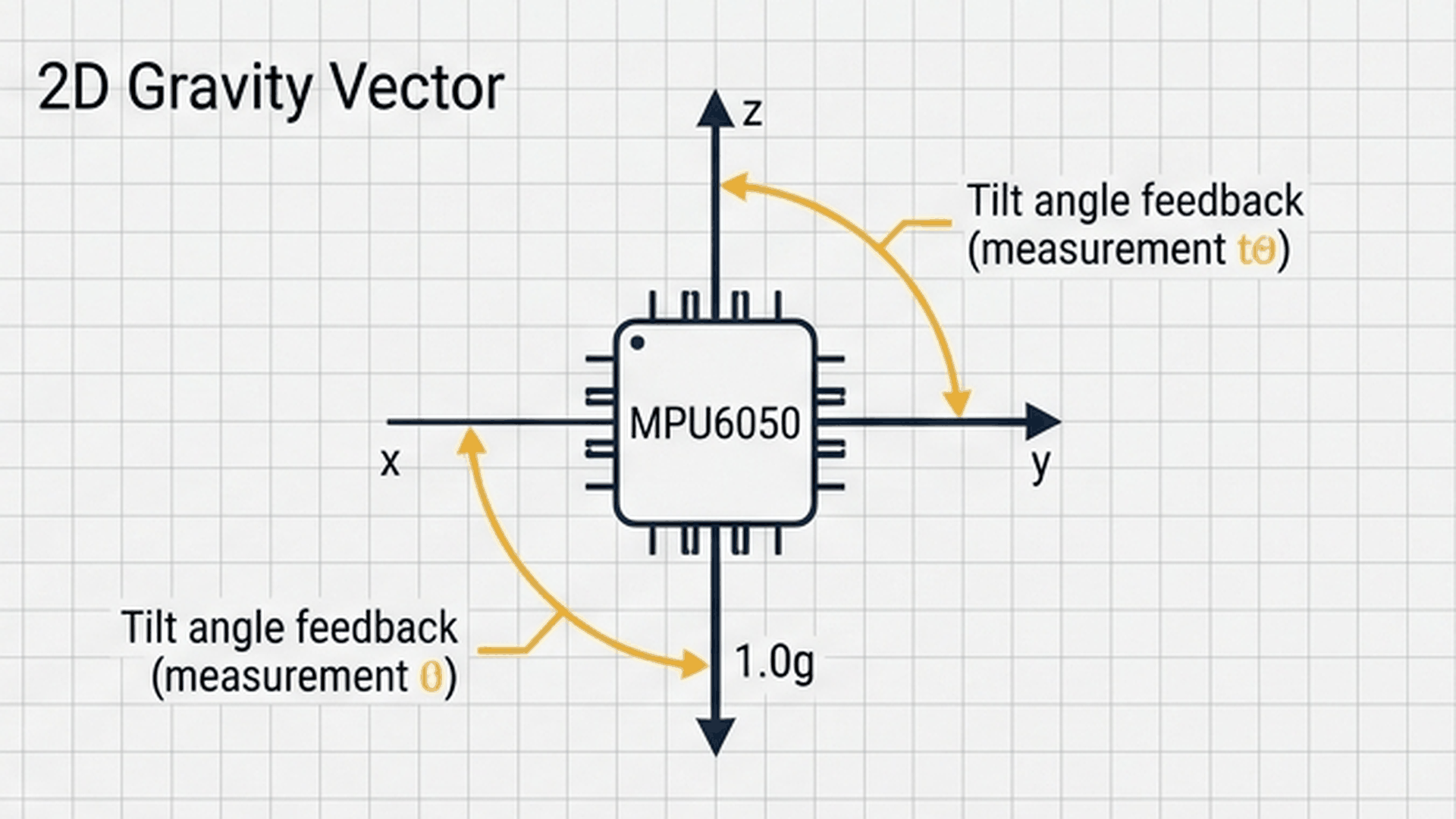
The diagram above illustrates the three primary orientations. When the sensor sits completely flat on a table, all 9.8 m/s² of gravity acts along the vertical Z-axis, while the horizontal X and Y axes read close to zero. When you tip the board forward or backward (Pitch), gravity bleeds into the X-axis. When you lean it left or right (Roll), gravity shifts into the Y-axis.
| Sensor position | X-axis acceleration | Y-axis acceleration | Z-axis acceleration |
|---|---|---|---|
| Flat & Level | Near 0.0 m/s² | Near 0.0 m/s² | ~9.8 m/s² (Downwards) |
| Tilted forward/back (Pitch) | > 3.0 m/s² | Near 0.0 m/s² | Reduced (~8.5 m/s²) |
| Tilted left/right (Roll) | Near 0.0 m/s² | > 3.0 m/s² | Reduced (~8.5 m/s²) |
| Dual diagonal tilt | > 3.0 m/s² | > 3.0 m/s² | Reduced (~7.0 m/s²) |
Setting a threshold of 3.0 m/s² corresponds to a tilt angle of approximately 18 degrees. Any tilt greater than this triggers the state change in firmware, ignoring minor table vibrations while catching intentional hand movements.
Showing Tilt States with an RGB LED
To make the orientation visible at a glance without reading text on a computer screen, the project uses a common-cathode RGB LED as a multi-color status beacon. Four clear visual states tell you whether the board is level or leaning.
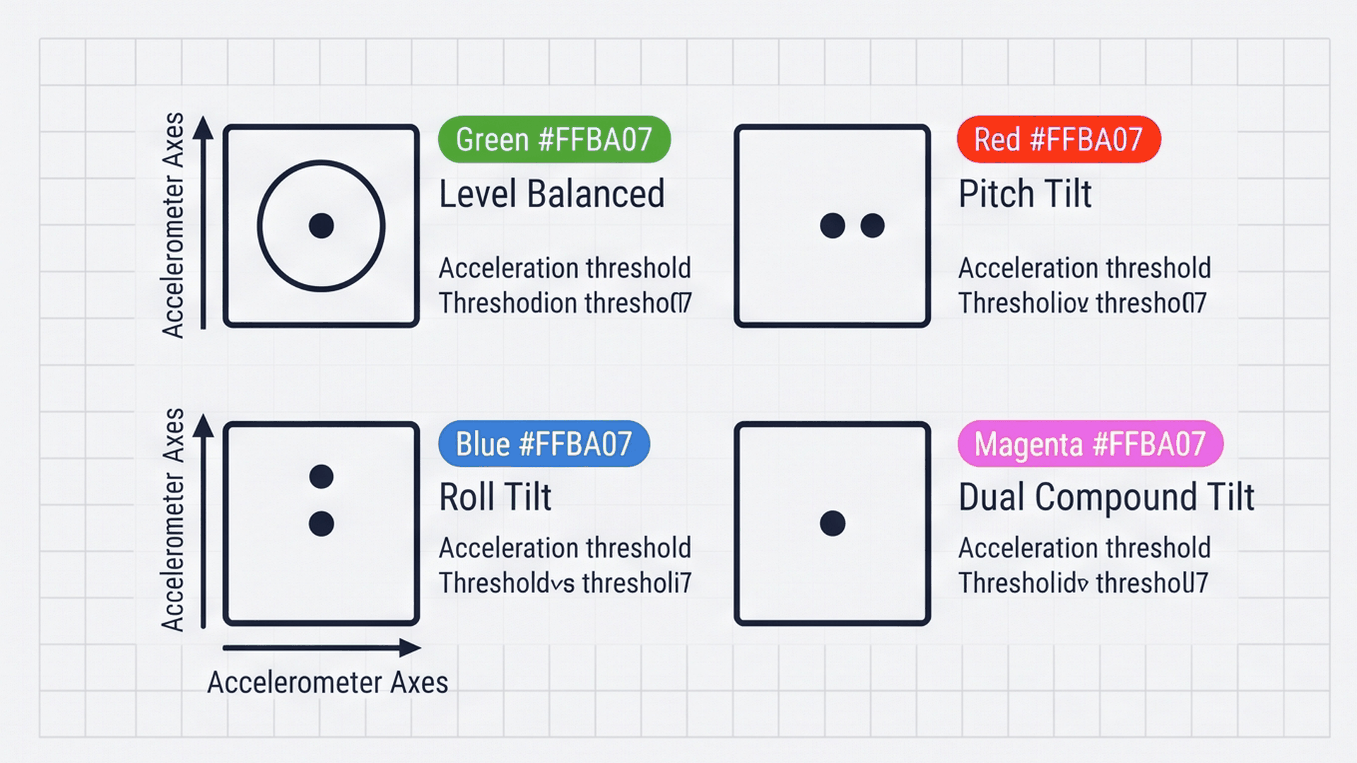
The visual above shows the four color states. When both axes are below the 3.0 m/s² threshold, the LED shines solid green to confirm the board is level. Tilting along the Pitch axis switches the LED to solid red. Tilting along Roll switches it to blue. If the board is tilted diagonally along both axes at once, the red and blue channels turn on together to create magenta.
| Orientation state | Tilt condition | Active LED color | Active pins |
|---|---|---|---|
| Level / Balanced | Both |X| and |Y| ≤ 3.0 m/s² | Solid Green | GPIO 4 (Green) |
| Pitch Tilt | |X| > 3.0 m/s², |Y| ≤ 3.0 m/s² | Solid Red | GPIO 3 (Red) |
| Roll Tilt | |X| ≤ 3.0 m/s², |Y| > 3.0 m/s² | Solid Blue | GPIO 5 (Blue) |
| Dual Tilt | Both |X| and |Y| > 3.0 m/s² | Magenta (Purple) | GPIO 3 (Red) + GPIO 5 (Blue) |
This direct optical feedback makes the sensor feel alive and responsive, providing immediate feedback in robotics, gaming controllers, or leveling gauges.
Connecting the Circuit
Think of this project like a digital carpenter's spirit level. When the surface is perfectly flat, the system stays calm with a green light; the moment something tips or falls over, the alert light changes immediately.
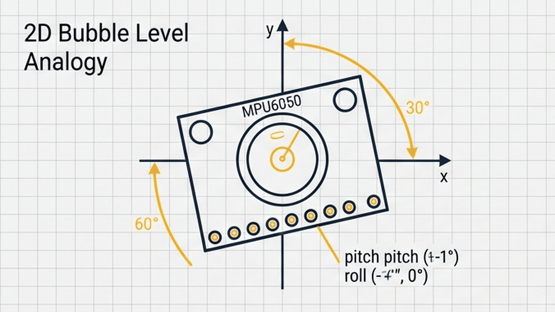
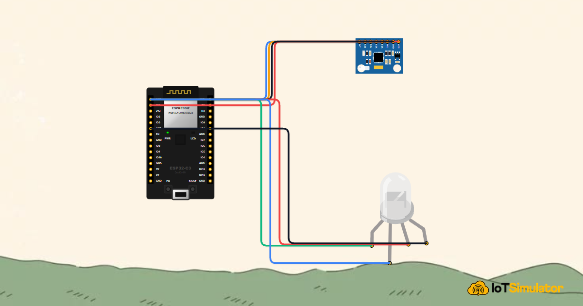
As shown in the illustration, the MPU6050 acts as the digital bubble, detecting orientation changes instantly. Connect the motion sensor module and RGB LED indicator as detailed below:
Next, wire the three color channels of the RGB LED indicator to GPIO 3, GPIO 4, and GPIO 5 to visually display tilt orientation:
The MPU6050 operates on 3.3V power. Connecting it to 5V could damage the sensitive internal MEMS silicon. Always verify that VCC connects to the 3.3V rail on the ESP32-C3.
Complete Code
Upload the following sketch to your ESP32-C3 DevKit. It initializes the I2C bus, configures the MPU6050 sensor's internal low-pass filter, and continuously updates the RGB LED while streaming telemetry to the serial console.
// ============================================================================
// ESP32-C3 6-Axis Motion & Tilt Tracker with MPU6050
// Demonstrates I2C IMU Telemetry, Gravitational Vectors & RGB State Feedback
// ============================================================================

#include <Wire.h>
#include <Adafruit_MPU6050.h>
#include <Adafruit_Sensor.h>

Adafruit_MPU6050 mpu;

const int RED_PIN   = 3; // GPIO 3 - Pitch Tilt Alert (Red)
const int GREEN_PIN = 4; // GPIO 4 - Level Stable Indicator (Green)
const int BLUE_PIN  = 5; // GPIO 5 - Roll Tilt Alert (Blue)

void setup() {
  Serial.begin(115200);
  while (!Serial && millis() < 2000);

  // Configure hardware I2C pins on ESP32-C3 (SDA: GPIO 8, SCL: GPIO 9)
  Wire.begin(8, 9);

  pinMode(RED_PIN, OUTPUT);
  pinMode(GREEN_PIN, OUTPUT);
  pinMode(BLUE_PIN, OUTPUT);

  Serial.println(F("===================================================="));
  Serial.println(F("  ESP32-C3 6-Axis Motion & Tilt Tracker Initializing"));
  Serial.println(F("===================================================="));

  if (!mpu.begin()) {
    Serial.println(F("[ERROR] Failed to detect MPU6050 sensor on I2C bus!"));
    while (1) { delay(100); }
  }

  mpu.setAccelerometerRange(MPU6050_RANGE_8_G);
  mpu.setGyroRange(MPU6050_RANGE_500_DEG);
  mpu.setFilterBandwidth(MPU6050_BAND_21_HZ);

  Serial.println(F("MPU6050 Sensor Calibrated & Online."));
}

void loop() {
  sensors_event_t a, g, temp;
  mpu.getEvent(&a, &g, &temp);

  // Evaluate tilt vectors along Pitch (X-axis) and Roll (Y-axis)
  // Threshold 3.0 m/s^2 corresponds to approximately 17.8 degrees tilt
  bool pitchHigh = abs(a.acceleration.x) > 3.0;
  bool rollHigh  = abs(a.acceleration.y) > 3.0;

  // Visual Orientation Mapping:
  // Level (Balanced) -> Solid Green
  // Pitch Tilt       -> Solid Red
  // Roll Tilt        -> Solid Blue
  // Dual Tilt        -> Magenta (Red + Blue)
  digitalWrite(RED_PIN, pitchHigh ? HIGH : LOW);
  digitalWrite(GREEN_PIN, (!pitchHigh && !rollHigh) ? HIGH : LOW);
  digitalWrite(BLUE_PIN, rollHigh ? HIGH : LOW);

  // Stream telemetry to Serial
  Serial.print(F("Accel [m/s^2] X: ")); Serial.print(a.acceleration.x, 2);
  Serial.print(F(" | Y: ")); Serial.print(a.acceleration.y, 2);
  Serial.print(F(" | Z: ")); Serial.print(a.acceleration.z, 2);
  Serial.print(F(" | Status: "));
  if (!pitchHigh && !rollHigh) Serial.println(F("[LEVEL]"));
  else if (pitchHigh && rollHigh) Serial.println(F("[DUAL TILT]"));
  else if (pitchHigh) Serial.println(F("[PITCH TILT]"));
  else Serial.println(F("[ROLL TILT]"));

  delay(100);
}
How the Code Works, Part by Part
The sketch coordinates between the sensor's I2C communications and output pin control. Here is how each section functions.
▸ Libraries and I2C Setup
The sketch starts by including Wire.h for I2C and the Adafruit_MPU6050 library to read the sensor.
#include <Wire.h>
#include <Adafruit_MPU6050.h>
#include <Adafruit_Sensor.h>

Adafruit_MPU6050 mpu;

const int RED_PIN   = 3;
const int GREEN_PIN = 4;
const int BLUE_PIN  = 5;
Assigning named constants to the output pins keeps the code readable and easy to adapt if pins change.
▸ Configuring the MPU6050 Sensor in setup()
Inside setup(), the code calls Wire.begin(8, 9) to route I2C signals to GPIO 8 (SDA) and GPIO 9 (SCL), then initializes the sensor.
Wire.begin(8, 9);

if (!mpu.begin()) {
  Serial.println(F("[ERROR] Failed to detect MPU6050!"));
  while (1) { delay(100); }
}

mpu.setFilterBandwidth(MPU6050_BAND_21_HZ);
The setFilterBandwidth(MPU6050_BAND_21_HZ) setting activates an on-chip digital filter that removes mechanical jitter and table vibrations, ensuring steady tilt readings.
▸ Reading Acceleration and Deciding Tilt States
In loop(), mpu.getEvent() reads the newest sensor measurements. The code tests whether either horizontal axis exceeds 3.0 m/s².
sensors_event_t a, g, temp;
mpu.getEvent(&a, &g, &temp);

bool pitchHigh = abs(a.acceleration.x) > 3.0;
bool rollHigh  = abs(a.acceleration.y) > 3.0;
Using abs() checks for tilt in either direction along an axis (forward or backward for Pitch, left or right for Roll).
▸ Controlling the RGB LED and Streaming Telemetry
Finally, the code drives the three LED pins based on the detected tilt states.
digitalWrite(RED_PIN, pitchHigh ? HIGH : LOW);
digitalWrite(GREEN_PIN, (!pitchHigh && !rollHigh) ? HIGH : LOW);
digitalWrite(BLUE_PIN, rollHigh ? HIGH : LOW);
The program repeats this measurement every 100 milliseconds (10 times per second), providing rapid, fluid visual feedback.
Fixing Common Problems
If the sensor fails to start or the LED shows incorrect colors, consult the quick solutions below.
| What you see | Likely cause | What to try |
|---|---|---|
| Serial says '[ERROR] Failed to detect MPU6050' | I2C wires swapped or loose connection | Ensure SDA is wired to GPIO 8 and SCL to GPIO 9; verify 3.3V power is connected |
| LED colors are inverted (LED turns off when it should turn on) | Common-anode LED used instead of common-cathode | Verify common leg connects to GND; common-anode LEDs need 5V and inverted HIGH/LOW logic |
| Colors flicker rapidly when board is barely moved | Sensor filter bandwidth disabled | Verify mpu.setFilterBandwidth(MPU6050_BAND_21_HZ) is present in setup() |
| LED stays green even when fully tilted | Threshold set too high in software | Confirm the condition checks 3.0 m/s² rather than raw integer sensor units |
The most common issue with I2C sensors is swapping the SDA and SCL wires. If the sensor is not found at startup, reversing those two pins will usually fix the issue immediately.
Try It in the Simulator
Click the Start Simulation (▶) button in the top toolbar to begin. The RGB LED will turn solid green to indicate the board is level. Click on the MPU6050 Sensor on the canvas to open its 3D rotation controls. Drag the tilt sliders along the Pitch and Roll axes to watch the LED switch between red, blue, and magenta in real time!