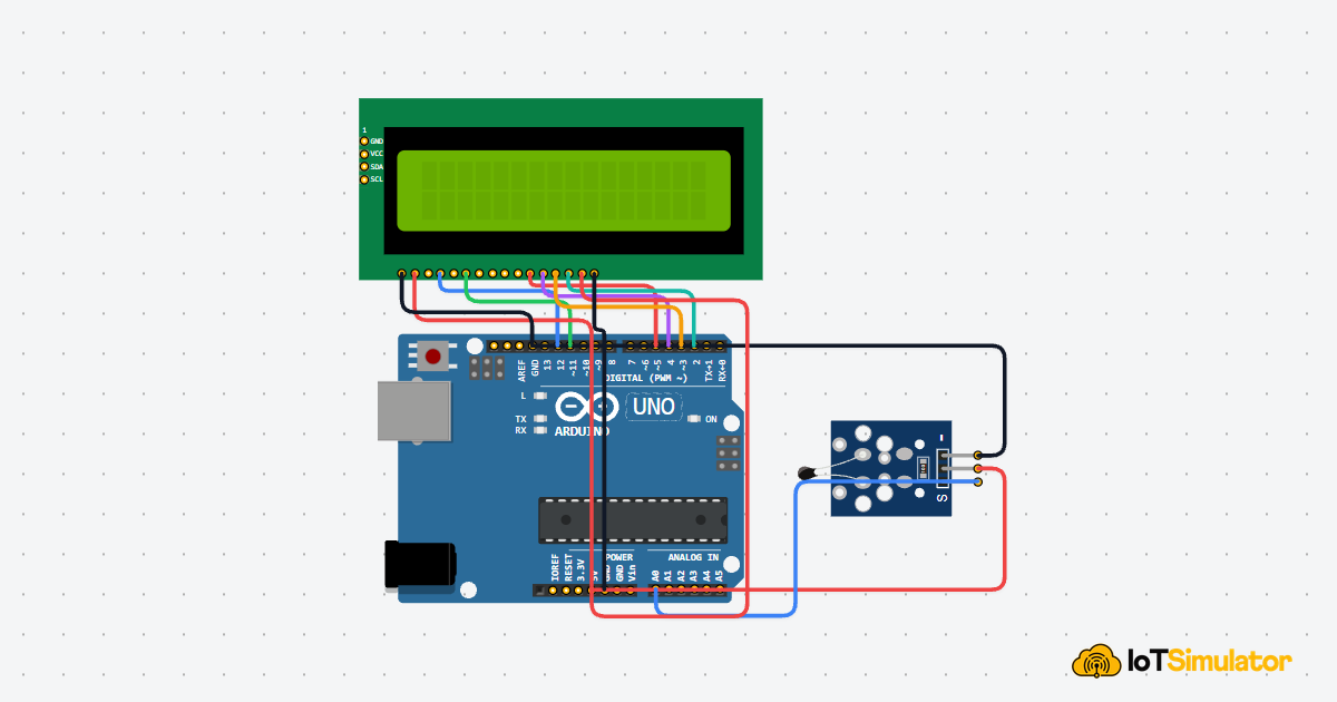
Display Temperature on an LCD with ESP32-C3

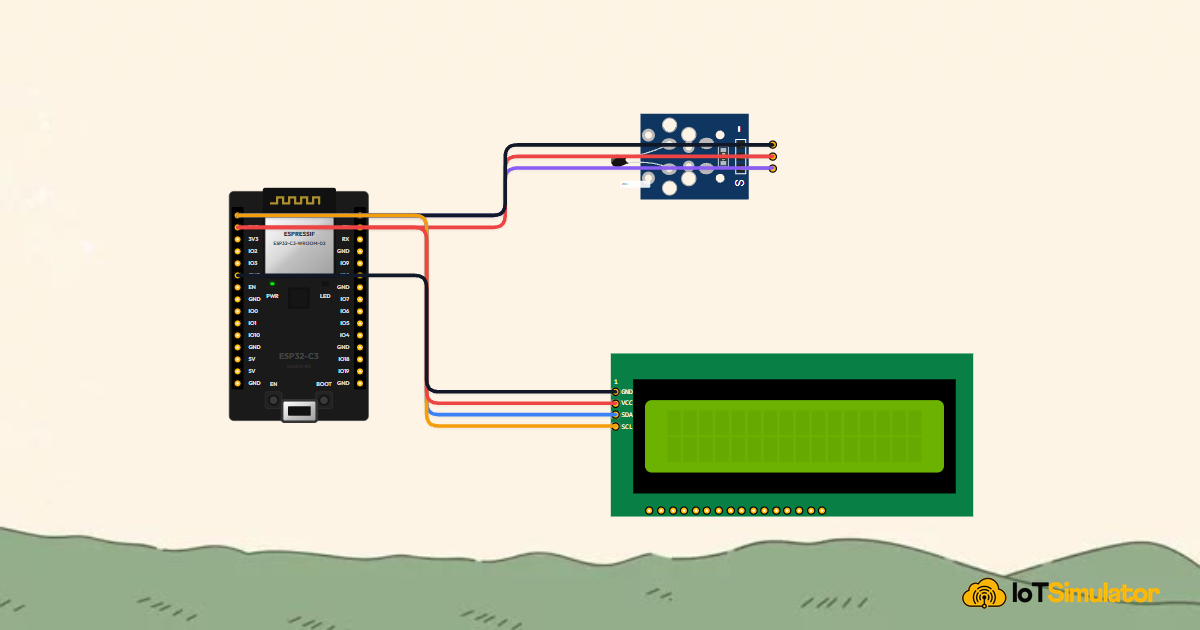
Live project track
A digital thermometer is one of the most practical instruments you can build. Whether monitoring a server room, a home greenhouse, or a 3D printer enclosure, having a clear live readout of temperature gives you immediate visibility into your environment. Instead of relying on a pre-packaged display, building your own teaches you how analog sensors translate physical heat into digital numbers.
In this project, you will build a digital weather station using an ESP32-C3 microcontroller, an NTC thermistor temperature sensor, and a 16x2 character LCD. The main idea is simple: the sensor changes its electrical resistance as the room warms up or cools down, the ESP32-C3's 12-bit analog converter reads that change, and the display shows live readings in both Celsius and Fahrenheit.
How the NTC Sensor Reads Heat
An NTC thermistor is a temperature-sensitive resistor whose name stands for Negative Temperature Coefficient. This means that as temperature increases, its electrical resistance drops. When wired with a fixed balancing resistor into a voltage divider circuit, changes in room temperature produce corresponding changes in output voltage.
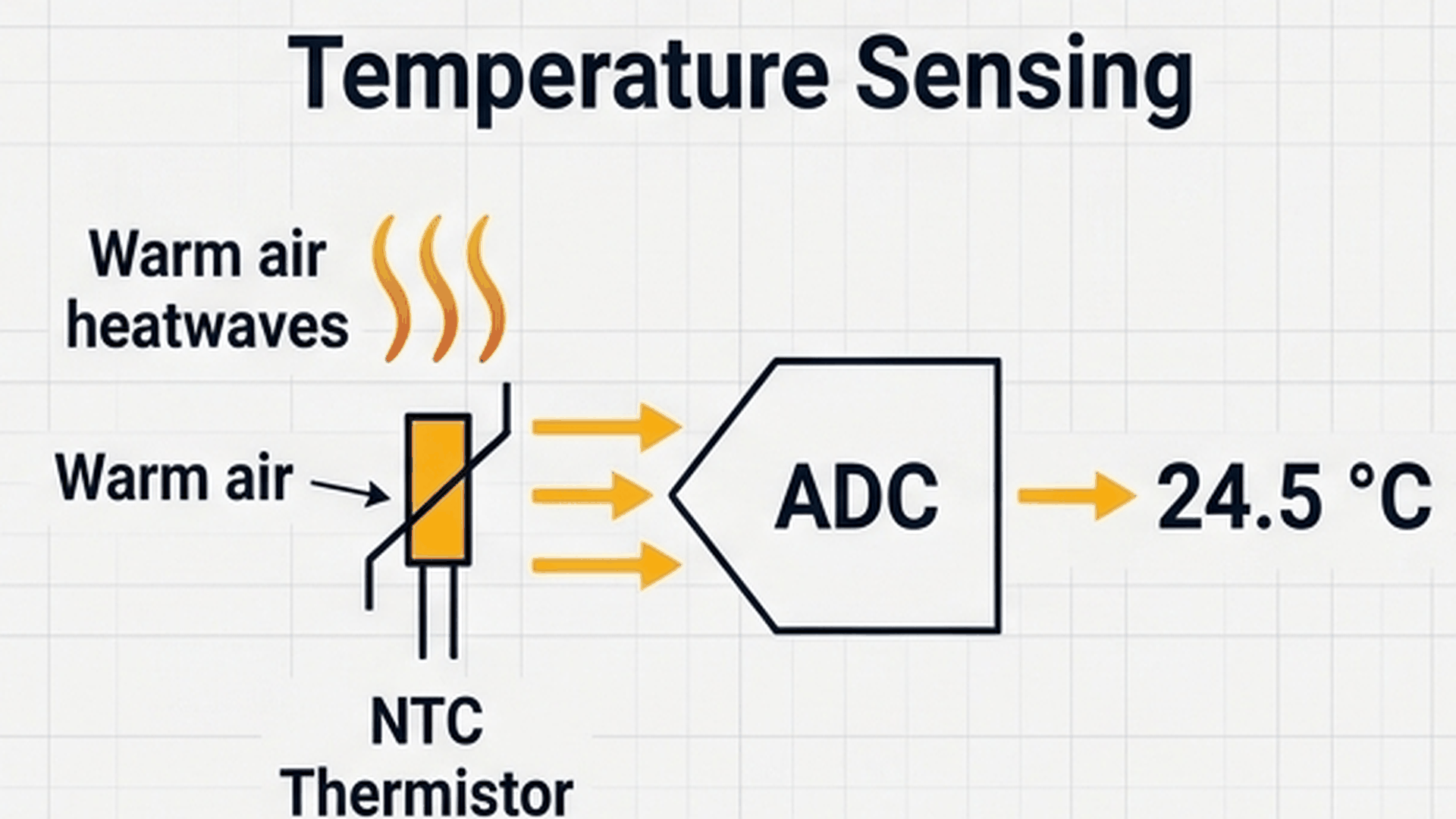
The diagram above illustrates how the measurement travels through the system. Ambient heat lowers the sensor resistance, which raises the voltage entering GPIO 0. The ESP32-C3's 12-bit analog-to-digital converter turns this voltage into an integer between 0 and 4095. Finally, the Steinhart-Hart equation translates that raw number into exact degrees.
| Room condition | Thermistor resistance | ADC reading (0–4095) | Calculated temperature |
|---|---|---|---|
| Cold (Refrigerated) | High (~30 kΩ) | ~1100 | ~5.0 °C (41.0 °F) |
| Room temperature | Medium (~10 kΩ) | ~2048 | ~25.0 °C (77.0 °F) |
| Warm / Hot | Low (~3 kΩ) | ~3200 | ~50.0 °C (122.0 °F) |
Because thermistor resistance follows a gentle curve rather than a straight line, our sketch uses the standard Beta equation to calculate the temperature accurately:
$$\frac{1}{T} = \frac{1}{T_0} + \frac{1}{\beta} \ln\left(\frac{R}{R_0}\right)$$
With a Beta coefficient of 3950, this formula accounts for the sensor's physical curve and delivers reliable decimal-degree measurements across the entire operating range.
Showing Readings on the I2C Screen
The LCD1602 display features two rows of text with 16 characters on each row. A bare LCD requires up to 16 separate wires to connect directly to a microcontroller. To avoid a tangled mess of wiring, this module includes an I2C backpack board that shrinks the connection down to just two signal wires: SDA (data) and SCL (clock).
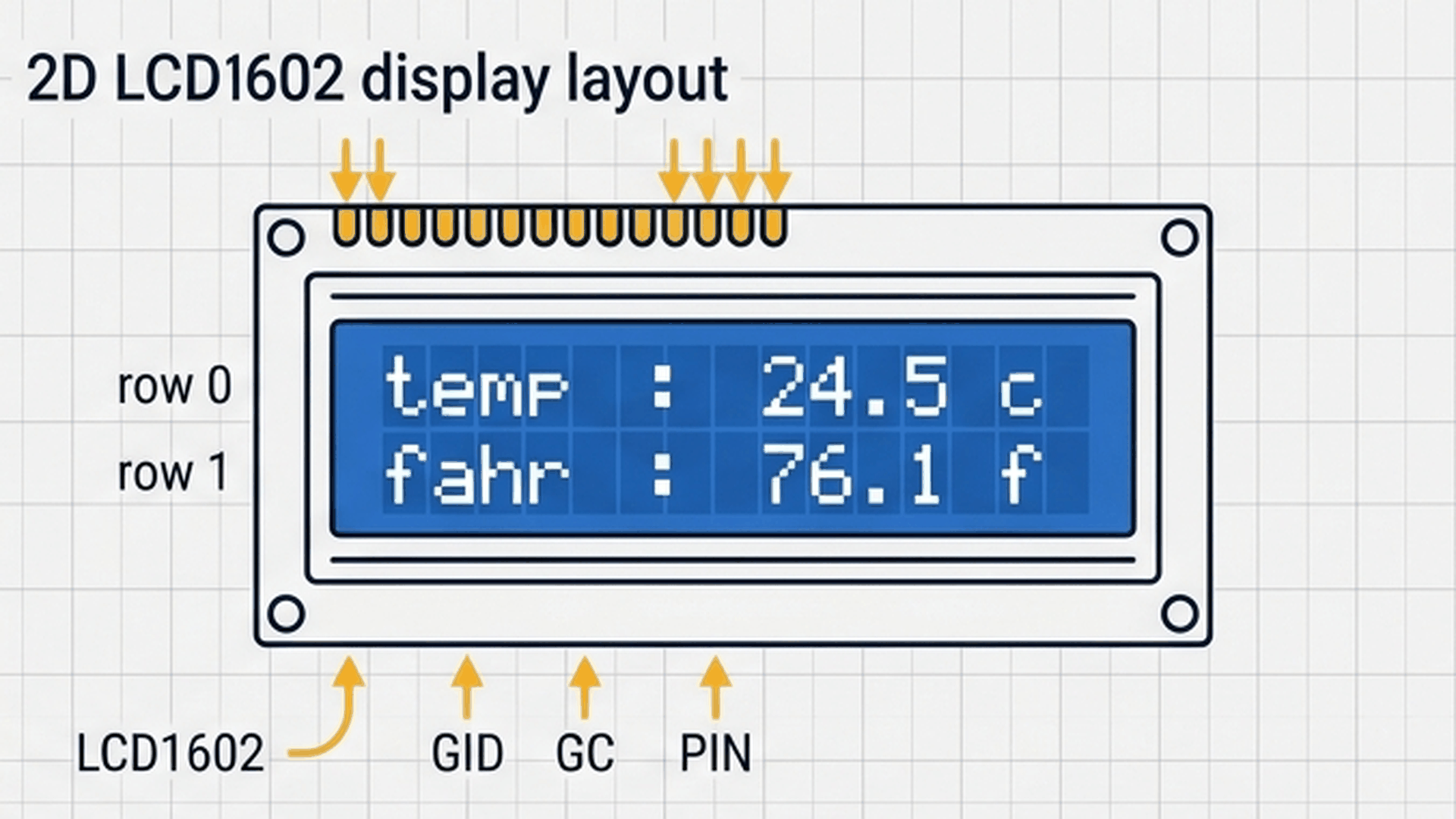
The diagram above shows the two display lines. Row 0 displays the temperature in Celsius, while Row 1 displays the reading in Fahrenheit. Both rows update once every second as new sensor readings arrive.
| Screen line | Grid coordinates | Displayed format | Example text |
|---|---|---|---|
| Line 1 (Top) | Column 0, Row 0 | Temp : XX.X C | Temp : 24.5 C |
| Line 2 (Bottom) | Column 0, Row 1 | Fahr : XX.X F | Fahr : 76.1 F |
Notice that the code prints extra spaces at the end of each line (" C ") instead of calling lcd.clear(). Calling lcd.clear() wipes the entire screen memory on every update, causing an annoying visual flicker. Printing trailing spaces overwrites older numbers smoothly while keeping the display solid and easy to read.
Connecting the Circuit
Bringing the sensor and display together follows a natural flow: the sensor captures room temperature, the microcontroller processes the reading, and the LCD presents the final value in real time.
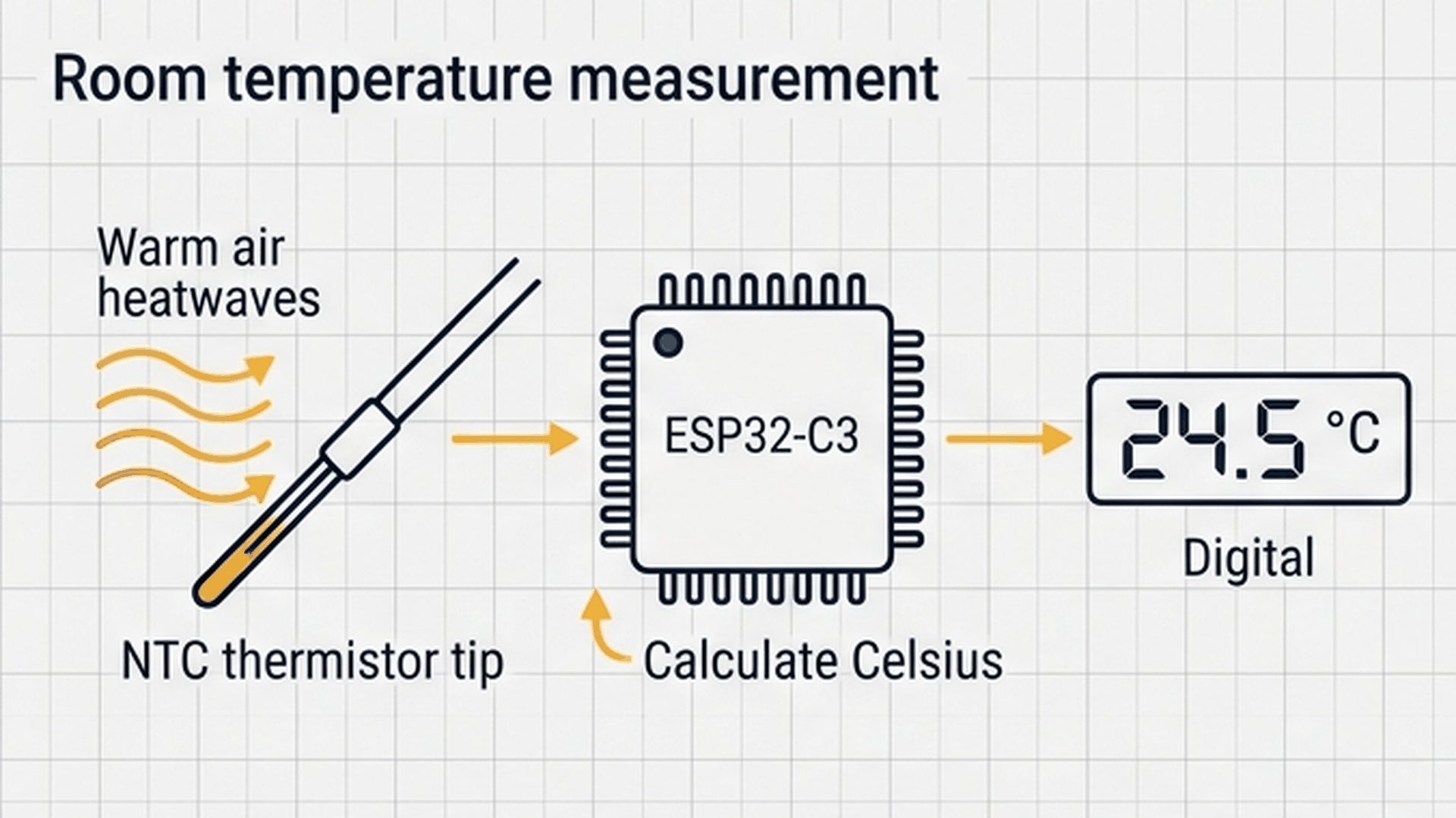
As shown in the flow diagram, each component handles one stage of the measurement pipeline. Wire the thermistor sensor module to provide analog voltage data and the I2C display to present the live results:
Next, connect the I2C LCD1602 display using its 4-pin interface to provide real-time temperature telemetry:
On the ESP32-C3, hardware I2C default pins are GPIO 8 for SDA and GPIO 9 for SCL. Explicitly calling Wire.begin(8, 9) in your setup routine ensures the microcontroller routes its internal I2C peripheral to the correct external pins before communicating with the screen.
Complete Code
Upload the following sketch to your ESP32-C3 DevKit. It initializes the I2C bus, shows a welcome banner, and starts streaming continuous live temperature measurements to the screen and the serial console.
// ============================================================================
// ESP32-C3 Precision Digital Thermometer with LCD1602
// NTC on GPIO 0 (ADC1_CH0) | I2C LCD on SDA: GPIO 8, SCL: GPIO 9
// ============================================================================
#include <Wire.h>
#include <LiquidCrystal_I2C.h>

// I2C LCD configuration (0x27 address, 16 columns, 2 rows)
LiquidCrystal_I2C lcd(0x27, 16, 2);

// NTC analog signal on ADC1_CH0 (GPIO 0)
const int ntcPin = 0;
const float BETA = 3950.0;

void setup() {
  Serial.begin(115200);

  // ESP32-C3 default hardware I2C pins: SDA=GPIO 8, SCL=GPIO 9
  Wire.begin(8, 9);

  lcd.init();
  lcd.backlight();

  lcd.setCursor(0, 0);
  lcd.print("ESP32-C3 Station");
  lcd.setCursor(0, 1);
  lcd.print("Initializing...");
  delay(1200);
  lcd.clear();
}

void loop() {
  // 12-bit ADC reads 0 to 4095 on 3.3V full-scale
  int rawADC = analogRead(ntcPin);
  if (rawADC <= 0) rawADC = 1;
  if (rawADC >= 4095) rawADC = 4094;

  // Beta equation for thermistor conversion
  float celsius = 1.0 / (log(1.0 / (4095.0 / rawADC - 1.0)) / BETA + 1.0 / 298.15) - 273.15;
  float fahrenheit = (celsius * 9.0 / 5.0) + 32.0;

  // Line 1: Celsius reading
  lcd.setCursor(0, 0);
  lcd.print("Temp : ");
  lcd.print(celsius, 1);
  lcd.print(" C   ");

  // Line 2: Fahrenheit reading
  lcd.setCursor(0, 1);
  lcd.print("Fahr : ");
  lcd.print(fahrenheit, 1);
  lcd.print(" F   ");

  // Telemetry output
  Serial.print("ADC: ");
  Serial.print(rawADC);
  Serial.print(" | Temp: ");
  Serial.print(celsius, 2);
  Serial.println(" °C");

  delay(1000);
}
How the Code Works, Part by Part
The sketch coordinates between hardware I2C communications and analog sensor math. Here is what happens in each section of the code.
▸ Libraries and Sensor Settings
The sketch starts by including Wire.h for I2C communication and LiquidCrystal_I2C.h to drive the display. It instantiates the display object at address 0x27 with 16 columns and 2 rows.
#include <Wire.h>
#include <LiquidCrystal_I2C.h>

LiquidCrystal_I2C lcd(0x27, 16, 2);

const int ntcPin = 0;
const float BETA = 3950.0;
The BETA constant represents the thermal curve value specified by the thermistor manufacturer (typically 3950 for standard 10k NTC sensors).
▸ Initializing the I2C Bus and Display
Inside setup(), the code opens the serial port and assigns the I2C pins. Calling Wire.begin(8, 9) configures GPIO 8 as SDA and GPIO 9 as SCL.
Wire.begin(8, 9);

lcd.init();
lcd.backlight();

lcd.setCursor(0, 0);
lcd.print("ESP32-C3 Station");
lcd.setCursor(0, 1);
lcd.print("Initializing...");
delay(1200);
lcd.clear();
The display turns on its blue backlight, shows a brief 1.2-second startup banner, and then clears the screen once before entering the main loop.
▸ Converting Sensor Readings to Real Temperatures
The ESP32-C3 features a 12-bit ADC, meaning analogRead(ntcPin) returns a number from 0 to 4095. The code clamps values at 1 and 4094 to avoid mathematical errors like division by zero or taking the logarithm of zero.
int rawADC = analogRead(ntcPin);
if (rawADC <= 0) rawADC = 1;
if (rawADC >= 4095) rawADC = 4094;

float celsius = 1.0 / (log(1.0 / (4095.0 / rawADC - 1.0)) / BETA + 1.0 / 298.15) - 273.15;
float fahrenheit = (celsius * 9.0 / 5.0) + 32.0;
Once the Celsius value is computed, converting to Fahrenheit is done with simple arithmetic: multiply by 9/5 and add 32.
▸ Updating the Screen Without Flickering
The code uses lcd.setCursor(0, 0) to position the cursor at the start of Row 0, then prints the temperature formatted to one decimal place.
lcd.setCursor(0, 0);
lcd.print("Temp : ");
lcd.print(celsius, 1);
lcd.print(" C   ");

lcd.setCursor(0, 1);
lcd.print("Fahr : ");
lcd.print(fahrenheit, 1);
lcd.print(" F   ");
The program repeats this update once every second using delay(1000), providing a steady, readable stream of data.
Fixing Common Problems
If the screen stays dark or the readings seem unusual, consult the troubleshooting guide below.
| What you see | Likely cause | What to try |
|---|---|---|
| LCD backlight is on but characters are blank | Contrast trimmer on I2C backpack is misaligned | Gently turn the small blue potentiometer on the back of the LCD until characters appear |
| Program freezes or crashes at startup | Missing I2C pin declaration | Ensure Wire.begin(8, 9) is called before lcd.init() |
| Temperature shows extreme negative values | Sensor pin disconnected or shorted to GND | Verify sensor OUT wire connects securely to GPIO 0 |
| Screen flickers or flashes every second | Using lcd.clear() inside the main loop | Remove lcd.clear() and print trailing spaces to overwrite digits cleanly |
The most common issue with I2C LCD displays is the contrast potentiometer. If your screen powers on with a blue glow but no letters appear, rotating the contrast screw on the backpack almost always solves the problem immediately.
Try It in the Simulator
Click the Start Simulation (▶) button in the top toolbar to begin. After the initial welcome message, the LCD screen will display real-time room temperature. Click the NTC Temperature Sensor on the canvas to open the temperature slider. Drag the temperature slider up and down to watch both Celsius and Fahrenheit numbers update smoothly on the screen!
More in ESP32-C3
More in Sensors
Build a Smart Climate Monitor with a Raspberry Pi Pico W
Build a Light Meter and Alarm with a Raspberry Pi Pico
Build a Multi-Room Safety Monitor with an Arduino Mega
Build a Motion Security Chime with an Arduino Nano