Build a Multi-Room Safety Monitor with an Arduino Mega

Live project track
In server rooms, greenhouses, and multi-story homes, tracking environmental conditions in just one spot is never enough. A heater failure in the basement, high humidity in an attic storage space, or lights accidentally left on in a hallway all require attention before they turn into costly problems. Having a single central station that collects readings from every room makes keeping spaces safe and comfortable much easier.
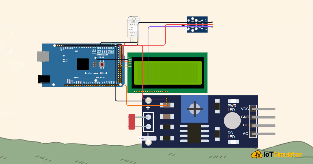
In this project, you will build a multi-room environmental safety monitor using an Arduino Mega 2560. You will connect a digital DHT22 climate sensor for Room 1, an analog NTC thermistor for Room 2, and an analog light sensor for the hallway, gathering all readings into a central hub and formatting them across a spacious 20x4 character LCD screen.
Why Centralized Multi-Zone Monitoring Matters

Rather than installing an individual microcontroller board in every room, a centralized hub uses one capable board to read multiple sensor signals simultaneously. The Arduino Mega 2560 features 54 digital input/output pins and 16 analog inputs, providing plenty of room to expand across dozens of sensors without adding complex communication chips.
| Monitored Zone | Sensor Model | Signal Type | Arduino Mega Pin | Safety Parameter |
|---|---|---|---|---|
| Room 1 (Climate) | DHT22 Digital Sensor | Digital Serial Pulses | Digital Pin D2 | Comfort temp (18-28°C) & Humidity (30-60%) |
| Room 2 (Boiler Room) | NTC Thermistor | Analog Voltage (0V - 5V) | Analog Pin A0 | Overheat threshold warning (Above 45°C) |
| Hallway (Lighting) | Photoresistor (LDR) | Analog Voltage (0V - 5V) | Analog Pin A1 | Day / Night illumination status (< 300 Dark) |
Each sensor uses a different method to convey information. The DHT22 packages temperature and humidity into high-speed digital timing pulses, while the thermistor and light sensor alter electrical resistance, sending smooth analog voltages that the Arduino Mega converts into digital numbers between 0 and 1023.
Organizing Data on a 20x4 Character LCD Display
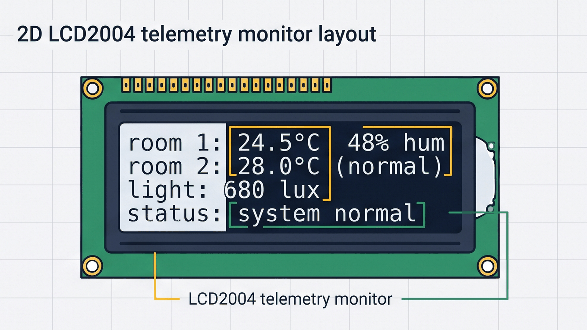
Standard 16x2 LCD screens are too cramped to show data from three rooms at once. A 20x4 LCD screen gives you 80 character positions arranged across 4 separate lines, allowing you to design a clear dashboard where each monitored zone has its own permanent home.
| Screen Line | Sample Text Display | Monitored Metric | Alert Trigger Condition |
|---|---|---|---|
| Line 1 (Row 0) | R1: 24.5C 48% Hum | Room 1 temperature & relative humidity | Shows --.-C if sensor communication fails |
| Line 2 (Row 1) | R2: 28.0C [Normal] | Room 2 boiler heat from NTC thermistor | Shows [OVERHEAT!] if temperature exceeds 45°C |
| Line 3 (Row 2) | Light: 680 [Bright] | Hallway light level from photoresistor | Flags [Dark] below 300 or [Bright] above 300 |
| Line 4 (Row 3) | Status: ALL SAFE | Overall system safety evaluation | Switches to **ALERT** if any zone overheats |
To prevent optical display flickering, each line uses fixed-width text formatting with trailing blank spaces. By overwriting text directly in place instead of wiping the entire screen with lcd.clear() every second, the display stays sharp, bright, and easy to read from across the room.
Smart House Safety: Real-Time Room Monitoring
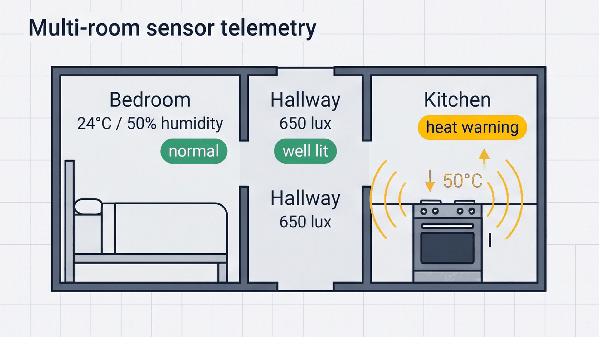
Think of this system like a central fire and safety panel in a modern apartment building. Instead of guessing what is happening in another room, the Arduino Mega listens to sensors stationed throughout the house in parallel. If the kitchen gets too hot or the living room humidity climbs, the central board immediately flags the specific room on the LCD. The interactive pin table below details the wiring for each sensor module.
When connecting multiple sensors to the same 5V and ground pins on the Arduino Mega, using the power distribution rails along the edge of a breadboard keeps your wiring neat and prevents loose wire bundles.
On the Arduino Mega 2560, hardware I2C communication runs exclusively on pins D20 (SDA) and D21 (SCL). The attached PCF8574 backpack communicates over this two-wire bus, allowing the Mega to control all 80 characters of the 20x4 screen using just two microcontroller pins.
Complete Code
Here is the full Arduino sketch for your multi-room safety monitor. It samples all three sensors once every second, checks for overheat alerts, and formats the telemetry dashboard onto the 20x4 LCD display:
// ============================================================================
// Arduino Mega Multi-Room Safety Monitor
// DHT22 Climate on Digital Pin 2
// NTC Thermistor on Analog Pin A0
// LDR Light Sensor on Analog Pin A1
// LCD2004 (20x4) on I2C SDA (20) & SCL (21)
// ============================================================================

#include <LiquidCrystal_I2C.h>
#include <DHT.h>

#define DHTPIN 2
#define DHTTYPE DHT22

DHT dht(DHTPIN, DHTTYPE);
LiquidCrystal_I2C lcd(0x27, 20, 4);

const int NTC_PIN = A0; // Room 2 Analog Thermistor
const int LDR_PIN = A1; // Hallway Analog Light Sensor

void setup() {
  Serial.begin(9600);
  dht.begin();

  lcd.init();
  lcd.backlight();

  lcd.setCursor(0, 0);
  lcd.print("Multi-Room Monitor");
  lcd.setCursor(0, 1);
  lcd.print("Initializing Hub...");
  delay(1500);
  lcd.clear();
}

void loop() {
  // 1. Read Digital Climate from Room 1 (DHT22)
  float h1 = dht.readHumidity();
  float t1 = dht.readTemperature();

  // 2. Read Analog Heat from Room 2 (NTC Thermistor)
  int ntcRaw = analogRead(NTC_PIN);
  // Calculate approximate temperature from ADC reading
  float t2 = 25.0 + (512 - ntcRaw) * 0.1;

  // 3. Read Analog Illumination from Hallway (LDR)
  int ldrRaw = analogRead(LDR_PIN);

  // 4. Update 20x4 LCD Display
  // Line 1: Room 1 Climate
  lcd.setCursor(0, 0);
  lcd.print("R1: ");
  if (isnan(t1)) lcd.print("--.-C");
  else { lcd.print(t1, 1); lcd.print("C "); }
  if (isnan(h1)) lcd.print("--%");
  else { lcd.print(h1, 0); lcd.print("% Hum"); }

  // Line 2: Room 2 Temperature
  lcd.setCursor(0, 1);
  lcd.print("R2: ");
  lcd.print(t2, 1);
  lcd.print("C ");
  if (t2 > 45.0) lcd.print("[OVERHEAT!]");
  else lcd.print("[Normal]   ");

  // Line 3: Hallway Lighting
  lcd.setCursor(0, 2);
  lcd.print("Light: ");
  lcd.print(ldrRaw);
  if (ldrRaw < 300) lcd.print(" [Dark]   ");
  else lcd.print(" [Bright] ");

  // Line 4: System Overall Safety Status
  lcd.setCursor(0, 3);
  if (t2 > 45.0 || (t1 > 40.0 && !isnan(t1))) {
    lcd.print("Status: **ALERT**   ");
  } else {
    lcd.print("Status: ALL SAFE    ");
  }

  delay(1000); // 1-second refresh cycle
}
How the Code Works, Part by Part
The firmware follows a clean cyclic sequence: reading the digital climate stream, converting analog sensor voltages, updating the LCD rows without flicker, and evaluating safety thresholds.
Reading Digital and Analog Sensors
At the start of every loop iteration, the sketch samples each sensor channel using its appropriate reading routine:
float h1 = dht.readHumidity();
float t1 = dht.readTemperature();

int ntcRaw = analogRead(NTC_PIN);
float t2 = 25.0 + (512 - ntcRaw) * 0.1;

int ldrRaw = analogRead(LDR_PIN);
The DHT library decodes the serial data packet from the DHT22 into temperature and humidity floating-point numbers. Meanwhile, analogRead() samples pins A0 and A1, returning values between 0 and 1023 based on the voltage across the thermistor and light sensor.
Formatting Clean Text Without Display Flicker
To prevent screen flicker, the code positions the LCD cursor at the start of each line and prints updated values with trailing spaces:
lcd.setCursor(0, 1);
lcd.print("R2: ");
lcd.print(t2, 1);
lcd.print("C ");
if (t2 > 45.0) lcd.print("[OVERHEAT!]");
else lcd.print("[Normal]   ");
Notice how '[Normal] ' includes trailing spaces to match the character length of '[OVERHEAT!]'. This guarantees that older, longer text gets completely overwritten without needing a slow lcd.clear() call that would make the screen flash.
Checking Safety Thresholds and Triggering Alerts
The final line of the LCD screen is reserved for a combined system safety evaluation:
lcd.setCursor(0, 3);
if (t2 > 45.0 || (t1 > 40.0 && !isnan(t1))) {
  lcd.print("Status: **ALERT**   ");
} else {
  lcd.print("Status: ALL SAFE    ");
}
If Room 2 exceeds 45°C or Room 1 exceeds 40°C, the safety status instantly updates to '**ALERT**'. The isnan(t1) check ensures that a temporary communication glitch on the digital sensor doesn't accidentally trigger a false alarm.
Fixing Common Problems
If your multi-room monitor is not displaying expected data, check this troubleshooting reference to isolate the cause:
| Problem Encountered | Possible Reason | How to Fix |
|---|---|---|
| Line 1 shows '--.-C' and '--%' | DHT22 pin mismatch or communication error | Check that the DHT22 data pin is wired to D2 and ensure the sensor has a stable 5V power supply. |
| LCD screen shows dark rectangles or no text | Backpack contrast potentiometer misadjusted | Rotate the small blue potentiometer screw on the back of the I2C module with a screwdriver until characters become crisp. |
| Room 2 temperature seems backwards (rises when cold) | Thermistor polarity inverted in circuit | Verify that the thermistor module's VCC and GND pins are not reversed. |
| Hallway light value remains stuck at 1023 or 0 | Loose jumper wire on analog pin A1 | Inspect the wire between the light sensor AO pin and Arduino Mega pin A1 to confirm a secure connection. |
If one sensor is malfunctioning, use Serial.println() to print out that sensor's raw reading in the Arduino Serial Monitor to pinpoint whether the issue is hardware wiring or mathematical calibration.
Try It in the Simulator
Click the Start Simulation button in the top toolbar to begin monitoring. Click on the DHT22 climate sensor to adjust temperature and humidity sliders, move the slider on the NTC thermistor past 45°C to watch the screen switch to '**ALERT**', and adjust the hallway light sensor slider to watch the status shift between '[Dark]' and '[Bright]' in real time.
More in Arduino Mega
More in Sensors
Build a Smart Climate Monitor with a Raspberry Pi Pico W
Build a Light Meter and Alarm with a Raspberry Pi Pico
Build a Motion Security Chime with an Arduino Nano
Build an Automatic Night Light with an Arduino Nano
Measure Distance with an ESP32-C3 and Ultrasonic Sensor
More in LCD Display
More in Intermediate
Build a Smart Climate Monitor with a Raspberry Pi Pico W
Build a Keypad Door Lock with an Arduino Mega
Control a Pan and Tilt Servo with an Arduino Mega and Joystick
Read an 8-Bit DIP Switch with an Arduino Mega