Build a Temperature Alarm with ATtiny85 and Buzzer

Live project track
Think about how a temperature alarm protects a computer, a 3D printer, or a battery pack. When heat builds up past a safe limit, a buzzer sounds and a red light flashes so you can cool down the equipment before anything is damaged.
In this project, you will build an automatic temperature alarm using an 8-pin ATtiny85 microcontroller, an NTC temperature sensor, an LED, and a buzzer. The main idea is simple: the sensor changes its resistance as temperature rises, and the ATtiny85 triggers an alarm when the reading crosses a safety threshold.
How the NTC Sensor Detects Temperature Changes
An NTC thermistor is a special kind of resistor whose resistance changes with heat. The letters NTC stand for Negative Temperature Coefficient. That simply means: as temperature goes up, electrical resistance goes down.
Because the sensor is wired with a fixed resistor on its module, this change in resistance creates a changing output voltage. The ATtiny85 reads that voltage on its analog pin as a number from 0 to 1023.
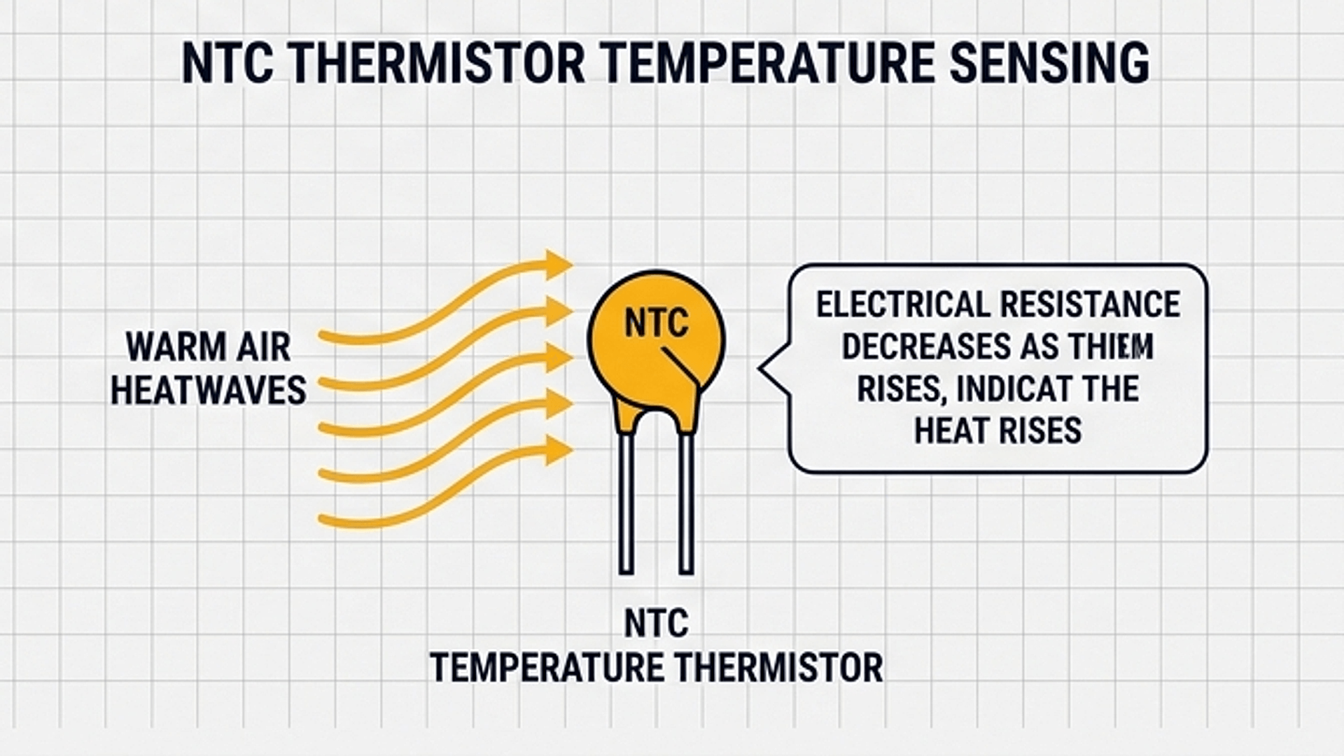
The diagram above illustrates how heat alters the sensor output. At normal room temperature, resistance is high and the voltage sits around 2.5V. When hot air or a warm finger heats the sensor, resistance drops, pulling the voltage down below 1.5V.
| Temperature State | Sensor Resistance | Analog Voltage | Alarm Response |
|---|---|---|---|
| Room Temp (25°C) | High (~10 kΩ) | ~2.5V (ADC ~512) | Safe (LED off, buzzer silent) |
| Warm (35°C) | Medium (~6 kΩ) | ~1.8V (ADC ~470) | Safe (LED off, buzzer silent) |
| Overheat (>45°C) | Low (<4 kΩ) | <1.5V (ADC <450) | Alarm Active (Flashing & Beeping) |
Because lower numbers mean higher heat in this setup, the code checks if the reading falls below 450 to detect when the temperature becomes too hot.
How the ATtiny85 Triggers the Flashing Alarm
The ATtiny85 continuously checks the sensor reading. When everything is cool and safe, both the LED and buzzer remain turned off to save power.
When the reading drops below the safety limit, the ATtiny85 enters the alarm state. It turns on the red LED and sends a clear 2000Hz beep through the buzzer, then turns them off and repeats every 200 milliseconds to create an urgent warning flash.
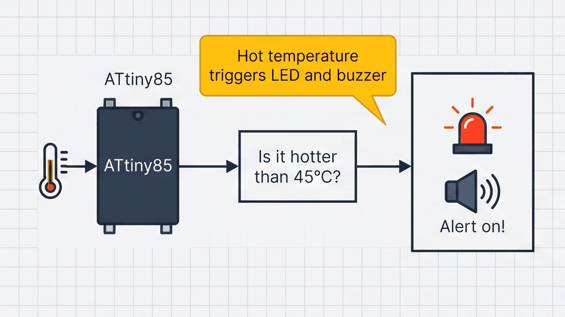
The process diagram above summarizes the three-step cycle: the sensor reads heat, the ATtiny85 compares it against the safety limit, and the output pins flash the LED and beep the buzzer when heat is detected.
GND is the electrical return path back to the ATtiny85. Connecting the sensor, LED, and buzzer to a shared ground reference ensures all signals are measured against the same 0V level.
Wiring the Sensor, LED, and Buzzer
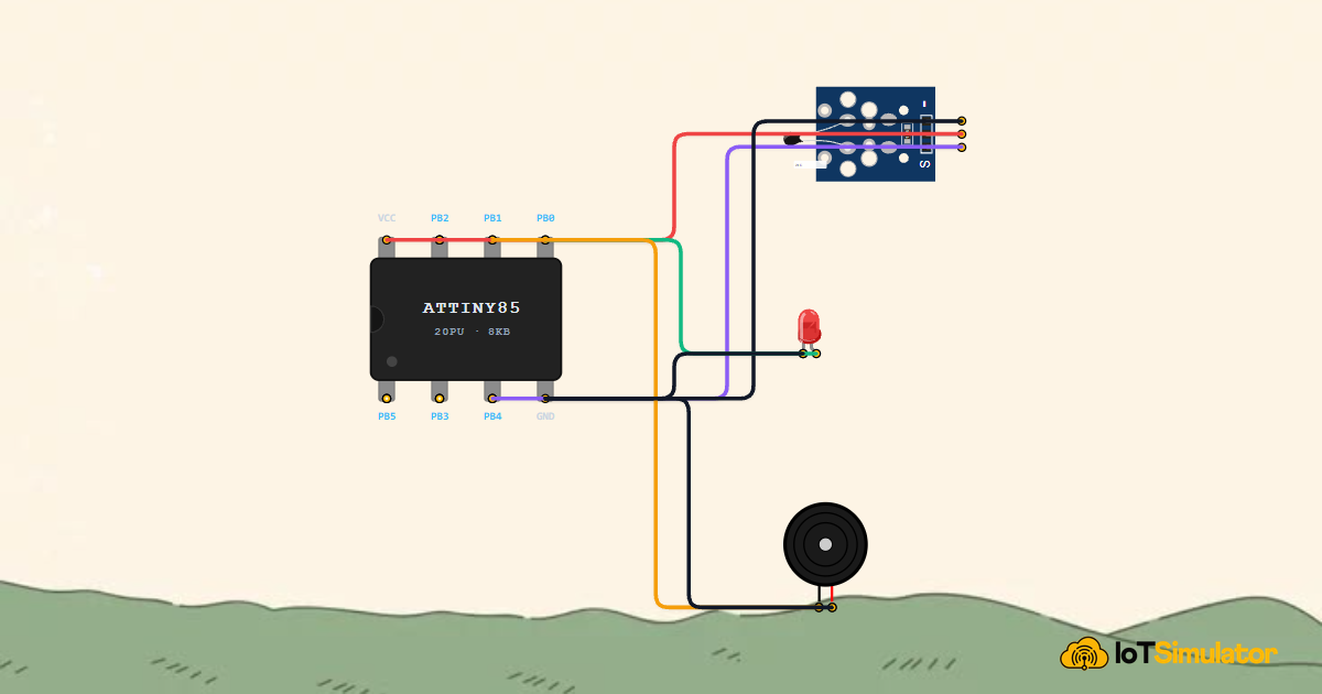
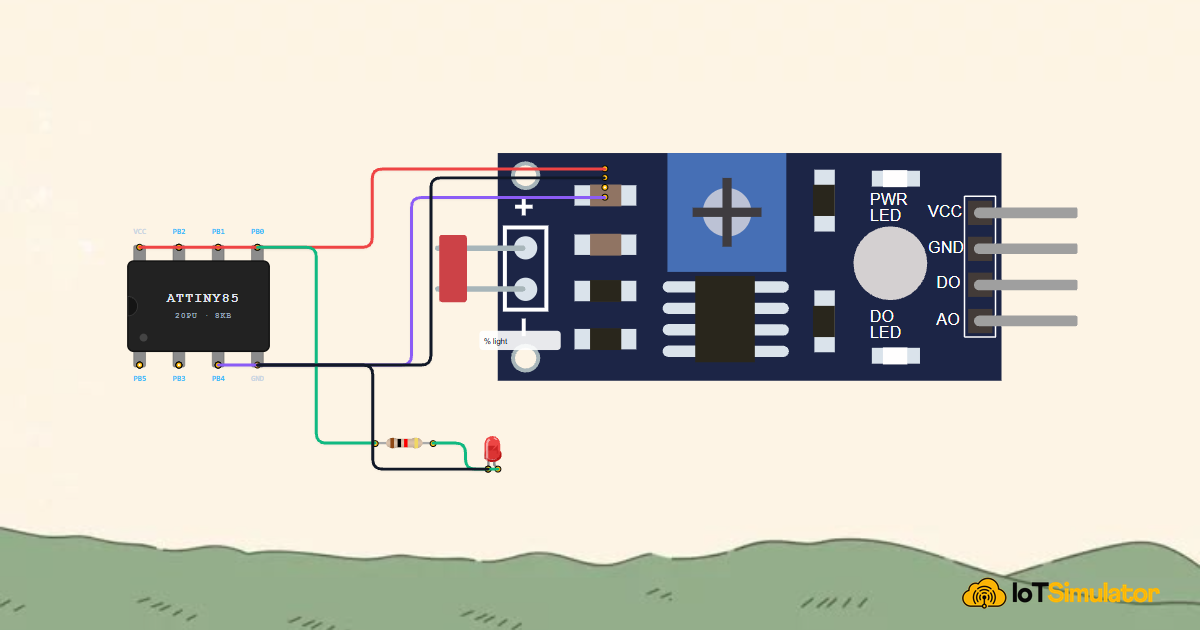
The ATtiny85 has 8 physical pins. Pin 8 provides positive 5V power, Pin 4 connects to ground, Pin 3 reads the analog sensor, Pin 5 drives the LED, and Pin 6 sounds the buzzer.
Next, wire the red warning LED anode to physical pin 5 (PB0) through a 220Ω resistor to provide immediate visual over-temperature alerts:
Finally, connect the piezo buzzer to physical pin 6 (PB1) so the circuit emits an audible warning chirp whenever the temperature threshold is crossed:
Double-check the LED orientation before powering on. The longer leg is the positive Anode and connects to Pin 5 (PB0), while the shorter flat side is the Cathode and connects to ground.
The Complete Temperature Alarm Sketch
Here is the full sketch for the ATtiny85. It continuously reads the sensor, checks the safety threshold, and runs the flashing alert when heat rises.
// ============================================================================
// ATtiny85 Overheat Alarm with Buzzer
// Reads NTC Thermistor on Physical Pin 3 (PB4 / ADC2 / Analog A2)
// Drives Warning LED on Pin 5 (PB0) and 2kHz Buzzer on Pin 6 (PB1)
// ============================================================================

const int NTC_PIN   = A2; // PB4 (Physical Pin 3 on DIP-8) - Thermal Sensor Input
const int LED_PIN   = 0;  // PB0 (Physical Pin 5 on DIP-8) - Warning LED Output
const int BUZZ_PIN  = 1;  // PB1 (Physical Pin 6 on DIP-8) - Buzzer Alert Output

// Overheat Threshold (ADC reading < 450 corresponds to approx > 45°C)
const int TEMP_THRESHOLD = 450;

void setup() {
  pinMode(LED_PIN, OUTPUT);
  pinMode(BUZZ_PIN, OUTPUT);
}

void loop() {
  // 1. Read temperature voltage from the thermistor (0 - 1023)
  int sensorVal = analogRead(NTC_PIN);

  // 2. Check if temperature exceeds the safety threshold
  if (sensorVal < TEMP_THRESHOLD) {
    // Active Overheat Alarm: 2kHz audio beep + flashing red LED
    digitalWrite(LED_PIN, HIGH);
    tone(BUZZ_PIN, 2000, 100); // 2000Hz beep for 100ms
    delay(100);
    digitalWrite(LED_PIN, LOW);
    delay(100);
  } else {
    // Normal Safe State: Keep alert devices quiet
    digitalWrite(LED_PIN, LOW);
    noTone(BUZZ_PIN);
    delay(300);
  }
}
▸ Naming Pins and Safety Threshold
The top lines name the input and output pins. A2 refers to analog channel 2 on physical pin 3. Setting TEMP_THRESHOLD = 450 defines the trip point where the alarm sounds.
const int NTC_PIN   = A2;
const int LED_PIN   = 0;
const int BUZZ_PIN  = 1;
const int TEMP_THRESHOLD = 450;
If you want the alarm to trigger at a lower temperature, increase this threshold number toward 480. To require more heat, decrease it toward 400.
▸ Setting Up Pin Modes in setup()
In setup(), the LED pin and buzzer pin are configured as outputs so the ATtiny85 can control them.
void setup() {
  pinMode(LED_PIN, OUTPUT);
  pinMode(BUZZ_PIN, OUTPUT);
}
The analog input pin does not need a pinMode statement because analogRead() configures the internal converter automatically.
▸ Checking Temperature in loop()
Inside loop(), analogRead() checks the current temperature. When the reading is below 450, the code flashes the LED and beeps the buzzer for 100 milliseconds.
if (sensorVal < TEMP_THRESHOLD) {
  digitalWrite(LED_PIN, HIGH);
  tone(BUZZ_PIN, 2000, 100);
  delay(100);
  digitalWrite(LED_PIN, LOW);
  delay(100);
} else {
  digitalWrite(LED_PIN, LOW);
  noTone(BUZZ_PIN);
  delay(300);
}
When the temperature cools down, the else block turns off the LED and stops the buzzer, returning the device to quiet monitoring.
More in ATtiny85
More in Sensors
Build a Smart Climate Monitor with a Raspberry Pi Pico W
Build a Light Meter and Alarm with a Raspberry Pi Pico
Build a Multi-Room Safety Monitor with an Arduino Mega
Build a Motion Security Chime with an Arduino Nano
Build an Automatic Night Light with an Arduino Nano
More in Intermediate
Build a Smart Climate Monitor with a Raspberry Pi Pico W
Build a Multi-Room Safety Monitor with an Arduino Mega
Build a Keypad Door Lock with an Arduino Mega
Control a Pan and Tilt Servo with an Arduino Mega and Joystick